Dehumidifying shoe cabinet

A technology for shoe cabinets and dehumidifiers, which is applied in the field of shoe cabinets, can solve problems such as odor generation and damp shoe cabinets, and achieve the effects of dehumidification, dryness maintenance, and user experience improvement

Inactive Publication Date: 2015-11-18
诸葛明
View PDF3 Cites 1 Cited by
  • Summary
  • Abstract
  • Description
  • Claims
  • Application Information

AI Technical Summary

Problems solved by technology

[0002] The traditional shoe cabinet is still lacking in dehumidification, especially in the rainy spring, the inside of the

Method used


Image

  • Dehumidifying shoe cabinet

Examples


Embodiment Construction

[0016] The principles and features of the present invention will be described below with reference to the accompanying drawings. The examples cited are only used to explain the present invention, and not used to limit the scope of the present invention.

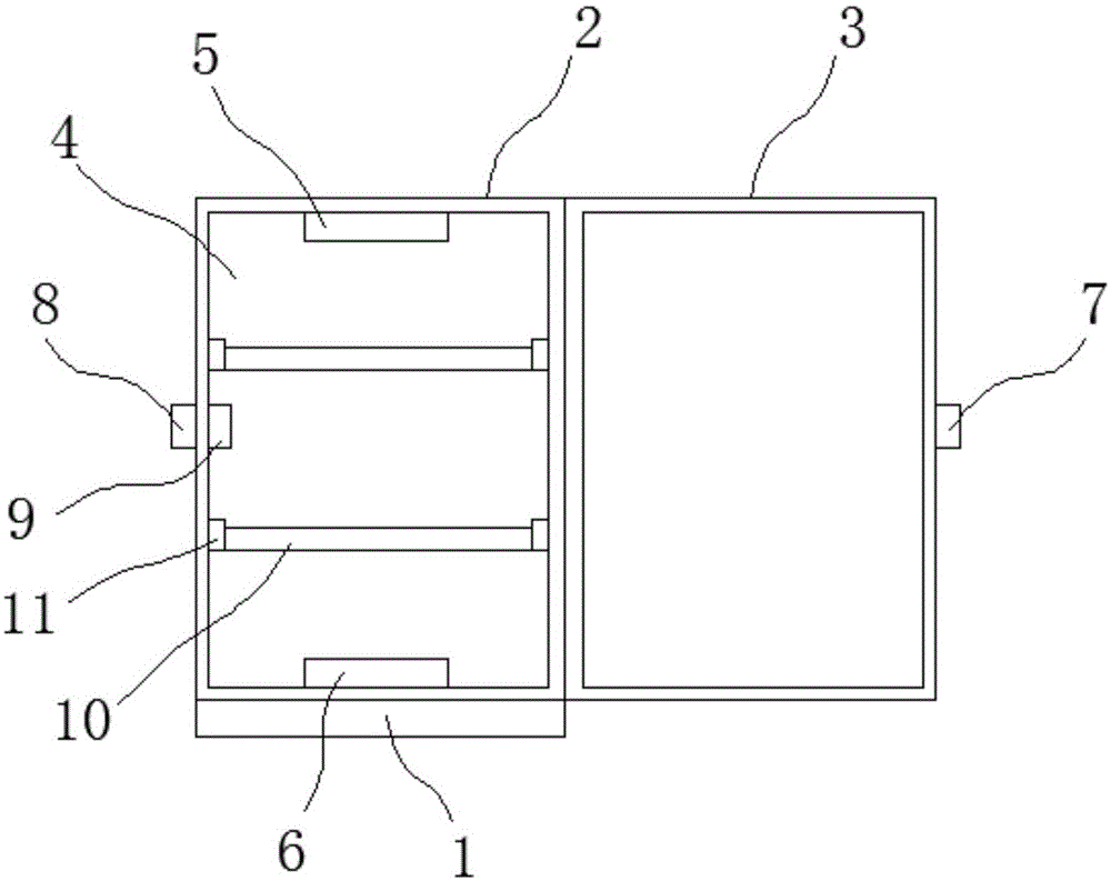
[0017] Such as figure 1 As shown, a dehumidifying shoe cabinet includes a base 1 and a shoe cabinet body 2. The shoe cabinet body 2 is placed on the upper end of the base 1, and the shoe cabinet body 2 is fixed on the upper end of the base 1, so The front end of the shoe cabinet body 2 is hingedly connected with a cabinet door 3, the inner side of the shoe cabinet body 2 is provided with a cavity 4 for accommodating shoes, and the top of the cavity 4 is provided with a detachable aromatherapy box 5. A dehumidifier 6 is provided at the bottom end of the cavity 4.

[0018] Preferably, a first magnetic block 7 is provided on the side of the cabinet door 3 away from its connection with the shoe cabinet body 2, and the shoe cabinet bo...


PUM


Abstract

The invention relates to a dehumidifying shoe cabinet which comprises a base and a shoe cabinet body, wherein the shoe cabinet body is fixedly arranged at the upper end of the base, the front end of the shoe cabinet body is connected with a cabinet door by a hinge, a cavity for containing shoes is arranged at the inner side of the shoe cabinet body, the top end of the cavity is provided with a detachable aromatherapy box, and the bottom end of the cavity is provided with a dehumidifier. Compared with the prior art, the dehumidifying shoe cabinet is simple in structure, and can effectively dehumidify, and provide aromatherapy.

Description

Technical field [0001] The invention relates to the technical field of shoe cabinets, in particular to a dehumidifying shoe cabinet. Background technique [0002] Traditional shoe cabinets are still lacking in dehumidification, especially in the spring and rainy days. The inside of the shoe cabinet is often humid, which will produce peculiar smells over time, so it is necessary to solve these problems. Summary of the invention [0003] The technical problem to be solved by the present invention is to provide a shoe cabinet with simple structure, effective dehumidification, and aromatherapy. [0004] The technical solutions of the present invention to solve the above technical problems are as follows: a dehumidifying shoe cabinet, comprising a base and a shoe cabinet body, the shoe cabinet body is placed on the upper end of the base, and the shoe cabinet body is fixed on the upper end of the base , The front end of the shoe cabinet body is hingedly connected with a cabinet door, the...

Claims


Application Information

Patent Timeline
IPC IPC(8): A47B61/04A47B57/06
Inventor 诸葛明
Owner 诸葛明
Why Eureka
Try Eureka