
A miniature electric sprayer

An electric sprayer and miniature technology, which can be applied to spray devices, single handheld devices, etc., can solve the problems of large frictional resistance, waste of energy, short battery life, etc., and achieve reduced contact area, convenient and fast operation, and extended service life. Effect

Active Publication Date: 2017-09-26
郭磊
View PDF7 Cites 0 Cited by
  • Summary
  • Abstract
  • Description
  • Claims
  • Application Information

AI Technical Summary

Problems solved by technology

Its disadvantages are: it is a flammable and explosive dangerous product, wastes energy, pollutes the environment, cannot be reused as a disposable product, and has a high cost of use. The advantages of both electric sprayer and manual sprayer and high-pressure aerosol tank: labor saving and safety , energy saving, environmental protection, reusable, conforming to the development trend of energy saving and environmental protection, it is an ideal product to replace high-pressure aerosol cans, but the current miniature electric sprayers have the disadvantages of complex structure, high production cost, and low work efficiency. Therefore, it is difficult to replace high-pressure aerosol cans
[0003] Check the Chinese patent literature, the electric sprayer of patent No. 200410062861.9, including motor, driving gear, transmission gear, cam, cam connecting shaft, pump, check valve, etc., its disadvantages: complex structure, relatively inconvenient production and assembly, high production cost, patent No. 200320114288.0 is a bottle-type miniature electric sprayer and 200620051396.3 bottle-type electric sprayer. Their common disadvantages are: due to the tight fit between the motor shaft and the motor shaft sealing ring, the frictional resistance is relatively large, resulting in a large working current of the motor and a short service life of the battery. , low work efficiency

Method used


Image

  • A miniature electric sprayer
  • A miniature electric sprayer
  • A miniature electric sprayer

Examples


Embodiment Construction

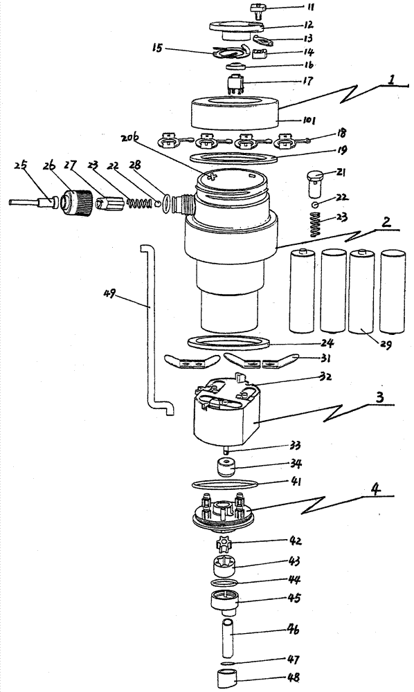
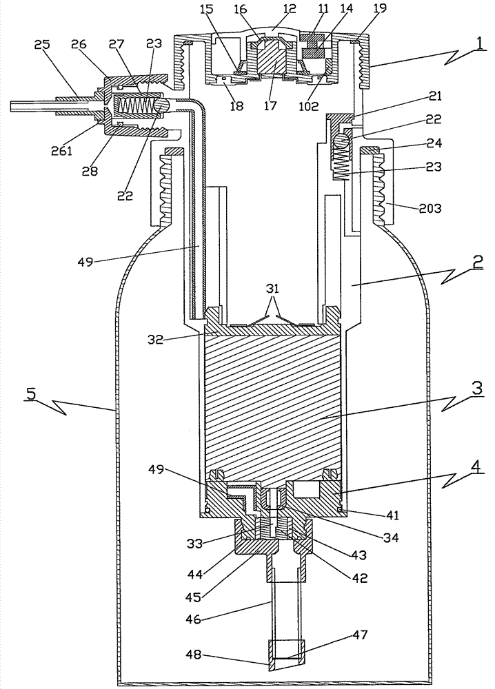
[0029] The main structural features, working principle and use of the miniature electric sprayer will be further described in conjunction with the accompanying drawings. please see figure 1 with figure 2 , a miniature electric sprayer, its structure from top to bottom, including battery box cover 1, main body 2, motor 3 and pump body 4 four parts, motor 3 and pump body 4 are located in the lower part of the main body 2. The battery case cover 1 is equipped with a button 12, an anti-maloperation switch assembly, a power switch 17, a battery connection piece 18, and the battery case cover 1 and the main body 2 are screwed or flipped. The main body 2 is cylindrical, and the inner cavity of the upper part of the main body 2 is a battery compartment 204 for placing a battery pack 29. There is a nozzle 202 on one side of the upper part of the main body 2, and a nozzle assembly and a nozzle cover 26 are installed on the nozzle 202. A waterproof sealing ring 41 is provided between ...


PUM


Abstract

Miniature electric sprayer, including battery box cover, main body, motor and pump body are located in the lower part of the main body, the container cover on the upper part of the main body is screwed to the liquid container, the button is installed on the battery box cover, and the inner cavity of the upper part of the main body is the battery compartment The battery pack is placed, there is a nozzle on the upper side of the main body, the nozzle assembly and the nozzle cover are installed on the nozzle, and a waterproof sealing ring is provided between the main body and the pump body; a power switch and a battery connecting piece are integrated in the battery box cover, and the battery box The button of the cover is provided with an anti-misoperation switch assembly, the battery box cover is threadedly connected with the main body or connected with a flip cover; the pump body is provided with an oil storage sealing ring, and the motor shaft passes through the center of the oil storage sealing ring. The product of the invention has the advantages of simple structure, low production cost, low energy consumption, fast operation, simple assembly, good spraying effect, wide application and high work efficiency.

Description

technical field [0001] The invention belongs to the technical field of sprayers, in particular to a miniature electric sprayer. Background technique [0002] Sprayers are widely used in people's daily life, such as killing pests, disinfection, beauty makeup, washing, cleaning and other occasions. Common sprayers on the market include manual sprayers, high-pressure aerosol tanks, and electric sprayers. Manual sprayer products have the advantages of safety, energy saving, environmental protection, and reusability. The disadvantages are that the spraying distance is short, continuous spraying is not possible, and it is laborious and inconvenient to use. High-pressure aerosol cans are convenient and quick to use. Common varieties include aerosol insecticides, aerosol air fresheners, aerosol cleaning agents, and industrial aerosol release agents. The working principle of high-pressure aerosol cans is to use high-vapor-pressure substances (such as chlorofluorocarbons, lower alkan...

Claims


Application Information

Patent Timeline
Patent Type & Authority Patents(China)
IPC IPC(8): B05B11/00
CPCB05B11/10B05B11/105
Inventor 郭磊
Owner 郭磊
Learn More