
Equipment used for machining three-dimensional externally finned tubes

A ribbed tube and equipment technology, which is applied in the field of equipment for processing three-dimensional outer ribbed tubes, can solve the problems of reducing the strength of the workpiece, heat dissipation effect, poor consistency of angle and thickness, etc.

Active Publication Date: 2015-11-18
CHONGQING HUIKUN ELECTRICAL APPLIANCE +1
View PDF7 Cites 10 Cited by
  • Summary
  • Abstract
  • Description
  • Claims
  • Application Information

AI Technical Summary

Problems solved by technology

[0004] The technical problem to be solved by the present invention is that the existing cutting tool used for processing three-dimensional outer ribbed pipe equipment adopts the ring gear to shrink and cut out the fins, and the depth, angle and thickness of the cut out fins are poor in consistency, thereby reducing the strength and Heat dissipation effect, providing a cutting tool with high consistency of fin depth, angle and thickness to avoid affecting the strength and heat dissipation effect of the workpiece for processing three-dimensional outer rib tube equipment

Method used


Image

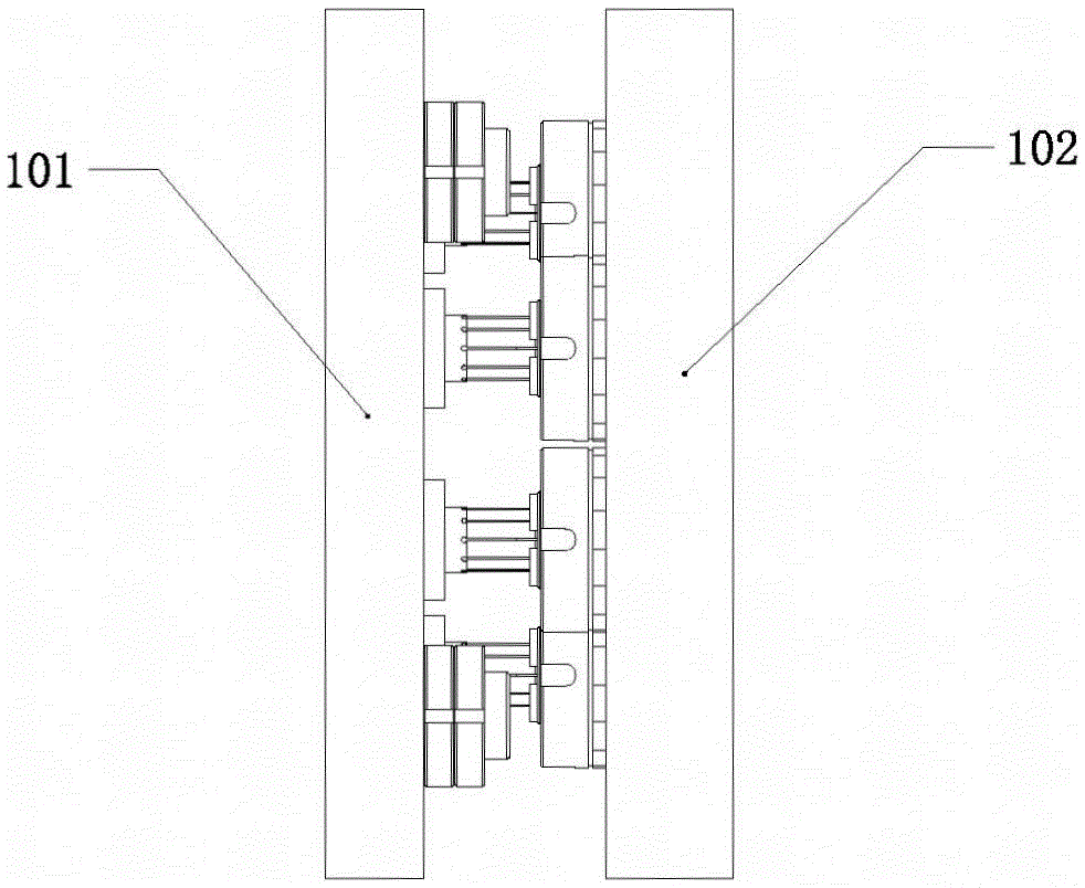
  • Equipment used for machining three-dimensional externally finned tubes
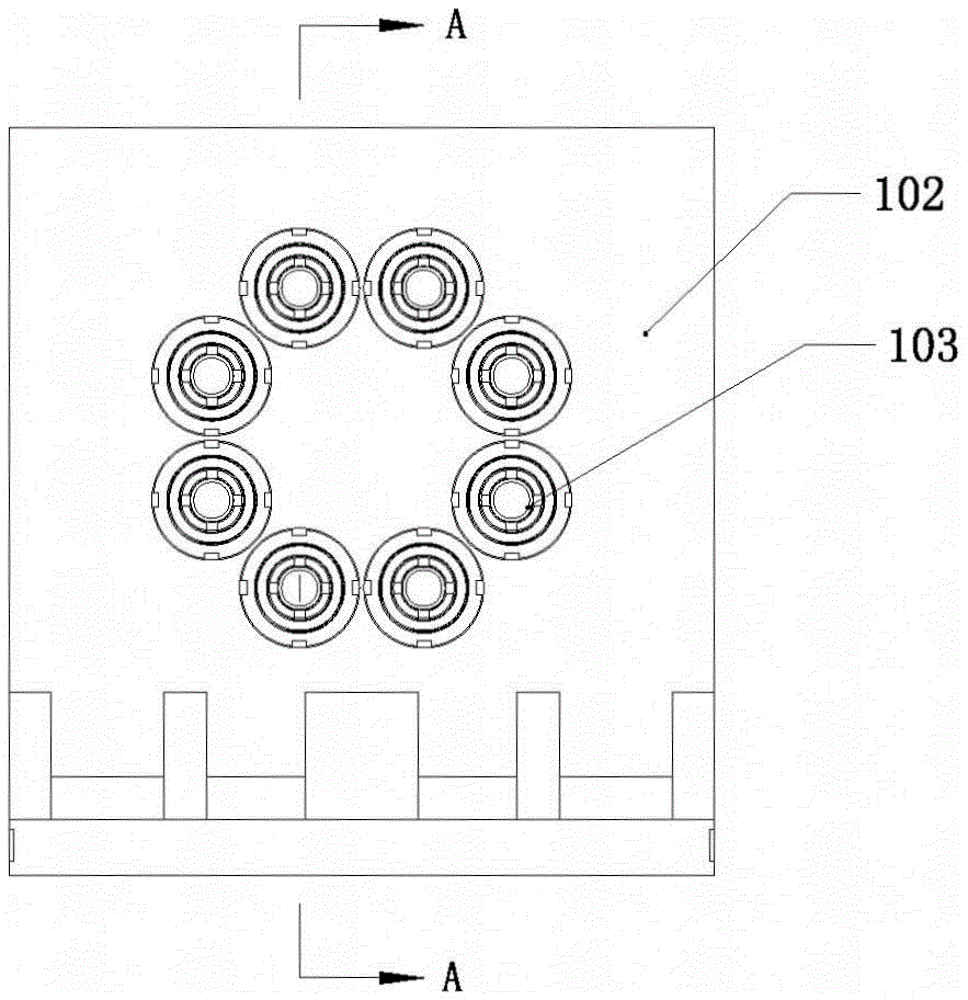
  • Equipment used for machining three-dimensional externally finned tubes
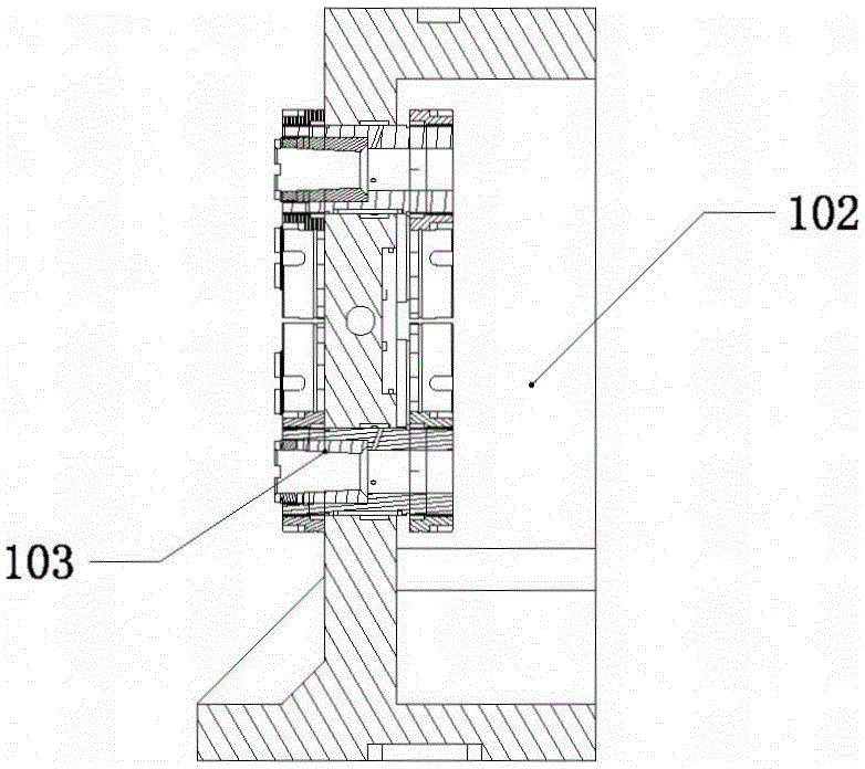
  • Equipment used for machining three-dimensional externally finned tubes

Examples


Embodiment 1

[0034] like Figure 9 , Figure 10 As shown: the workpiece feeding device 3 includes a sleeve 302 and a rotatable connecting rod 303, and also includes a fixed block 301. The end of the connecting rod 303 is connected with a connecting rod 304, and the front end of the connecting rod 303 is provided with a clamping platform 305, and the sleeve 302 is sleeved outside the connecting rod 303, the diameter of the card table 305 is greater than the diameter of the connecting rod 303, the outer wall of the card table 305 is threadedly connected with the workpiece, and the outer wall of the connecting rod 304 at the end of the connecting rod 303 is threadedly connected with a tensioning fixture; The outer wall of the front end of 302 and the outer wall of card table 305 are provided with the same thread, and the thread section of the inner wall of the workpiece is provided with two smooth sections 306 of pitch length. Between the front end of the barrel 302 and the card table 305; t...

Embodiment 2

[0037] Compared with the first embodiment of the workpiece feeding device 3, the oil cylinder 307 in the first embodiment is replaced by an air cylinder.

[0038] 4 embodiments of locking device in the present invention:

[0039] like Figure 11 Shown: the locking device 4 connected with the workpiece feeding device 3, the upper part of the frame 2 includes a slide rail 402 with a boss 401 on the inside or outside of the upper part, and the locking device 4 is located on the slide rail 402; the locking device 4 It includes a slider 403 that is slidably matched with the upper end of the boss 401 of the slide rail 402, a pressure block 404 that is slidably matched with the lower end of the boss 401 of the slide rail 402, a cylinder 405 and a spring 406 that are arranged on the slider 403, and the spring 406 One end is connected to the pressing block 404 , the other end of the spring 406 is connected to the sliding block 403 ; a sliding rod 407 is disposed inside the cylinder 40...


PUM

PropertyMeasurementUnit
Angleaaaaaaaaaa
Angleaaaaaaaaaa
Angleaaaaaaaaaa

Abstract

The invention discloses equipment used for machining three-dimensional externally finned tubes. The equipment used for machining the three-dimensional externally finned tubes comprises a rack, a cutter and a workpiece feeding device. The cutter comprises cutter bodies, an upper die and a lower die. The cutter bodies are longitudinally inlaid in the upper die. Cone-shaped sleeves are longitudinally inlaid in the lower die. Each cutter body comprises a cutter rest and a group of cutter teeth. Each group of the cutter teeth are radially arranged at the end of the corresponding cutter rest evenly, and space is reserved between every two cutter teeth. Each cutter tooth comprises a cutter blade portion and a cutter point portion. The cutter blade portions are connected with the cutter rests. Included angles are arranged between the cutter point portions and the cutter blade portions, and the cutter point portions are close to the axes of the cutter rests. The cutter point portions are close to the large diameter sides of the cone-shaped sleeves in the lower die. The cutter rests are far away from the large diameter sides of the cone-shaped sleeves. According to the equipment, the defects that the uniformity of the depths, angles and thicknesses of fins cut through a cutter of existing equipment used for machining three-dimensional externally finned tubes are low and the strength and heat dissipation effect of the tubes are lowered are overcome. The equipment used for machining the three-dimensional externally finned tubes comprises the cutter, and the uniformity of the depths, angles and thicknesses of the fins cut through the cutter are high.

Description

technical field [0001] The invention belongs to the field of turning devices, and in particular relates to a device for processing three-dimensional outer ribbed tubes. Background technique [0002] The three-dimensional outer rib tube is to cut three-dimensional fins on the outer wall of the tube, so as to improve the heat dissipation function. Existing three-dimensional externally ribbed tubes are usually fins arranged in an axial line. When processing the outer fins, the cutter teeth are inserted into the outer wall of the tube, and then pushed forward, the three-dimensional fins can be cut out on the outer wall of the tube, and then retreated to reset, repeating the previous action, while the tube itself moves forward, so that the outer wall of the tube Cut out the outer fins that line up neatly along the axial line. [0003] Chinese patent, the notification number is: CN203037126U, in order to strengthen the heat dissipation performance of the outer rib tube, the fins...

Claims


Application Information

Patent Timeline
IPC IPC(8): B23B5/08B23B25/00B23B27/00B23Q5/22B23Q5/52
CPCB23B5/08B23B25/00B23B27/00B23Q5/22B23Q5/52
Inventor 邱勇廖光亚彭程林
Owner CHONGQING HUIKUN ELECTRICAL APPLIANCE
Learn More