Automatic-feeding lathe tailstock mechanism

A technology of automatic feeding and driving mechanism, applied in the direction of tailstock/top, turning equipment, tool holder accessories, etc., can solve the problems of high labor intensity and low labor efficiency

Active Publication Date: 2015-11-18
扬州高力机械有限公司
View PDF7 Cites 4 Cited by
  • Summary
  • Abstract
  • Description
  • Claims
  • Application Information

AI Technical Summary

Problems solved by technology

This method is labor-intensive and low-efficiency for mass production of shaft holes, especially for through-holes.

Method used


Image

  • Automatic-feeding lathe tailstock mechanism
  • Automatic-feeding lathe tailstock mechanism
  • Automatic-feeding lathe tailstock mechanism

Examples


Embodiment Construction

[0057] The present invention will now be further described in detail in conjunction with the accompanying drawings and embodiments. These drawings are all simplified schematic diagrams, only illustrating the basic structure of the present invention in a schematic manner, so it only shows the composition related to the present invention.

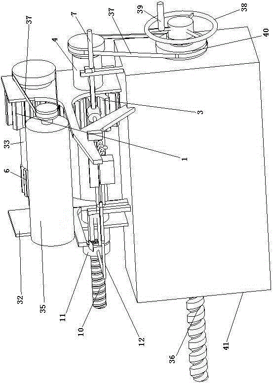
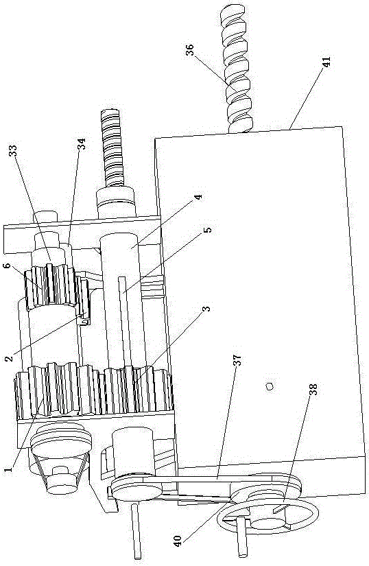
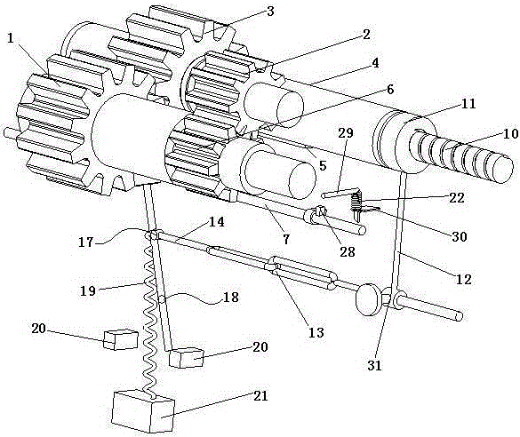
[0058] Such as Figure 1-5 As shown, a kind of automatic feed lathe tailstock mechanism includes: a frame body 32, and a drive mechanism and a toggle mechanism installed on the frame body 32, the drive mechanism and the toggle mechanism are connected by a fork lever 8, and the drive mechanism Driven by the power unit, the driving mechanism drives the drill bit 36 ​​to move,

[0059] The drive mechanism includes a drive gear 3 that can mesh with the first gear 1 and the second gear 2 respectively, the drive gear 3 is slidably arranged on the drive shaft 4, and the rotation direction of the first gear 1 and the second gear 2 is opposite; the to...


PUM


Abstract

The invention relates to an automatic-feeding lathe tailstock mechanism. The automatic-feeding lathe tailstock mechanism comprises a frame body and a driving mechanism and a pushing mechanism which are installed on the frame body; the driving mechanism and the pushing mechanism are linked through pushing fork rods, the driving mechanism is driven by a power device and drives a drill bit to act, and the driving mechanism can drive a driving gear to conduct forward rotation and reverse rotation; the pushing mechanism comprises a pushing rod which is arranged in a sliding mode, and the two pushing fork rods are located on the out sides of the two ends of the driving gear respectively; one end of a driving shaft is provided with a screw, and a thread sleeve connected with a curved rod is connected to the screw in a sleeving mode; an oscillating rod is connected with the pushing rod through a first rotating shaft and connected with a chain rod through a second rotating shaft, and the oscillating rod rotates through a third rotating shaft; the two ends of a chain are connected with the free end of the chain rod and the free end of the curved rod, and the free end of the chain rod and the free end of the curved rod can be in butt joint; one end of a first spring is fixedly connected to the portion, located on the position of the second rotating shaft, of the oscillating rod, and the other end of the first spring is fixedly connected to a fixing block; the pushing rod is further provided with a protruding block, and the protruding block is linked with a stopping mechanism.

Description

technical field [0001] The invention relates to a lathe tailstock, in particular to an automatic feeding lathe tailstock mechanism. Background technique [0002] Drilling on an ordinary lathe, the general method is to install the tapered shank of the drill in the tapered hole of the tailstock, fix the tailstock on the lathe guide rail, and then manually operate the hand wheel at the rear end of the tailstock to make the tailstock The seat cylinder advances along the axial direction of the drill bit to realize the translational feed of the drill bit; otherwise, the handwheel is reversed to make the tailstock cylinder retreat along the axial direction of the drill bit to realize the translational retraction of the drill bit. This method has high labor intensity and low labor efficiency for mass production of shaft holes, especially through holes. [0003] Therefore, for general drilling processing, especially large-scale through-hole processing, it is necessary to design a se...

Claims


Application Information

Patent Timeline
Patent Type & Authority Applications(China)
IPC IPC(8): B23B23/00
CPCB23B23/00
Inventor 陶杰
Owner 扬州高力机械有限公司
Why Eureka
Try Eureka