AI technical title is built by PatSnap AI team. It summarizes the technical point description of the patent document.
A technology of rotorcraft and rotors, which is applied in the field of aircraft to achieve the effects of low cost, strong wind resistance and low price
Inactive Publication Date: 2015-11-18
SUN HAWK HENAN AVIATION IND CO LTD
View PDF5 Cites 4 Cited by
Summary
Abstract
Description
Claims
Application Information
AI Technical Summary
This helps you quickly interpret patents by identifying the three key elements:
Problems solved by technology
Method used
Benefits of technology
Problems solved by technology
[0003] Although the autogyro has good safety performance, even in an emergency situation, it can use its superior gliding performance to find a suitable site for a safe landing, but under the premise of an emergency, not all pilots can make correct and reasonable operations to ensure the safety of all aircraft occupants
Method used
Image
Click on the blue label to locate the original text in one second.
Reading with bidirectional positioning of images and text.
Examples
Embodiment 1
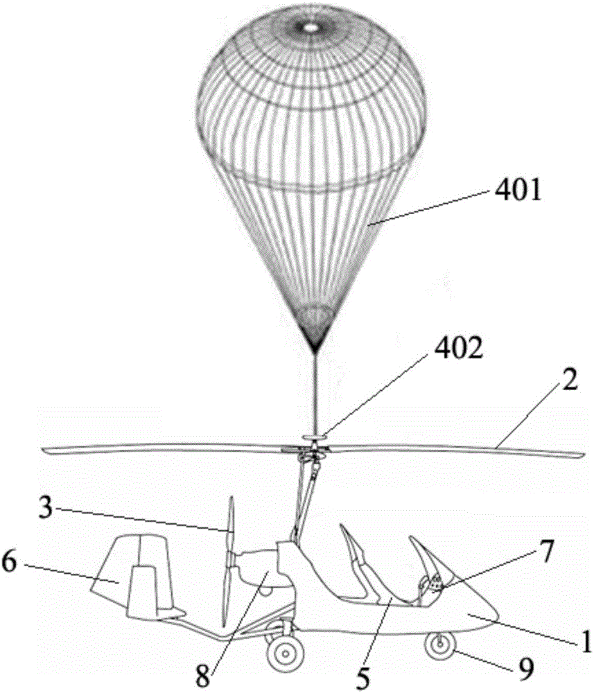
[0035] The present embodiment provides a parachute autogyro, which is characterized in that it comprises: a fuselage 1, a rotor device 2, a propeller device 3 and a parachute device 4, wherein,
[0036] The fuselage 1 includes a cockpit 5 and a tailrudder 6, a control system 7 is arranged at the front end of the cockpit 5, an engine 8 is arranged at the rear end of the cockpit 5, and a landing gear is also arranged below the fuselage 1 9;
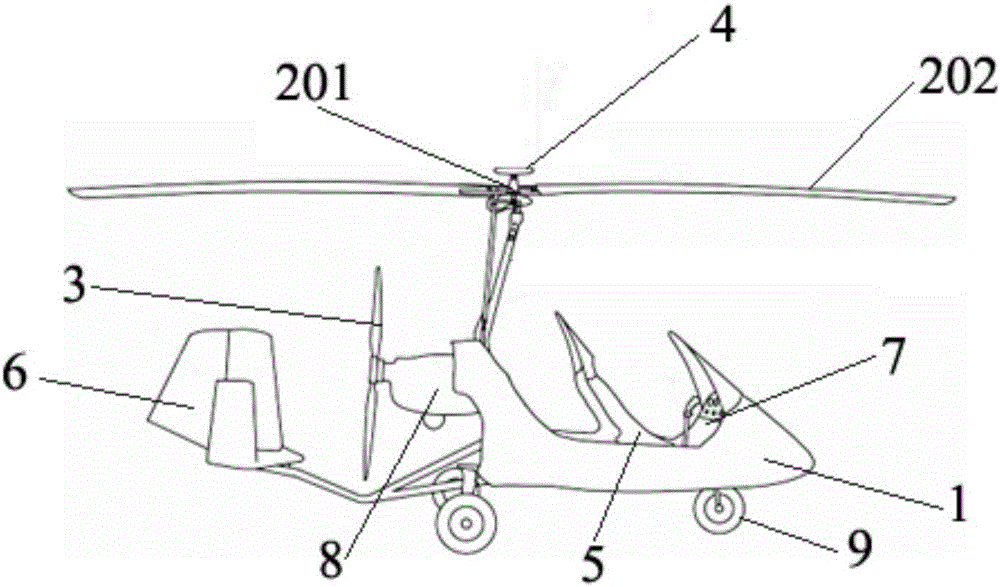
[0037] The rotor device 2 is arranged on the top of the fuselage 1, and includes a rotor head 201 and rotor blades 202 symmetrically arranged around the rotor head 201;
[0038] The screw device 3 is arranged at the tail of the cockpit 5, and it is connected with the engine 8 through a gear box;
[0039] The parachute device 4 is arranged above the rotor head 201 and includes a complete parachute 401 , a storage compartment 402 for accommodating the complete parachute, and a catapult for opening the parachute.
[0040] Further, the contr...
Embodiment 2
[0046] The present embodiment provides a method for parachuting an autogyro, characterized in that it comprises the following steps:
[0047] The parachute autogyro is set to include a fuselage, a rotor device, a propeller device and a parachute device, wherein,
[0048] The fuselage is provided with a cockpit and a tail rudder, a control system is arranged at the front end of the cockpit, an engine and a propeller are arranged at the rear end of the cockpit, and landing gear is arranged below the fuselage;
[0049] The rotor device is arranged on the top of the fuselage, and the rotor device is arranged to include a rotor head and rotor blades arranged symmetrically around the rotor head;
[0050]The propeller device is arranged at the tail of the cockpit, and is connected with the engine through a gear box;
[0051] The parachute device is arranged above the rotor head, and is configured to include a complete parachute, a storage compartment for accommodating the complete p...
PUM
Abstract
The invention discloses a parachuting autogyro. The parachuting autogyro comprises a fuselage, a rotor wing device, a screw propeller device and a parachute device, wherein the fuselage comprises a cabin and a tail vane; a control system is arranged at the front end of the cabin; an engine is arranged at the rear end of the cabin; an undercarriage is further arranged under the fuselage; the rotor wing device is arranged at the top of the fuselage and comprises a rotor wing head and rotor wing sheets which are symmetrically arranged at the periphery of the rotor wing head; the rotor wing device is arranged at the tail part of the cabin and is connected with the engine through a gear box; and the parachute device is arranged above the rotor wing head and comprises a complete machine parachute, a storage cabin for storing the complete machine parachute and a catapult for opening the parachute. The parachuting autogyro has the following effects (1) the safety is high; (2) a taking-off and landing distance is short; (3) the stability is high and the wind resistance is strong; and (4) the cost performance is relatively high.
Description
technical field [0001] The present application relates to the field of aircraft technology, in particular, to a parachute autogyro and a method thereof. Background technique [0002] Autogyro is a kind of rotorcraft with autorotator as lifting surface and propeller as forward power. Autogyro is actually a kind of aircraft between helicopter and fixed-wing aircraft, and it is removed outside rotor, also has a pair of screw propellers to provide the power that advances. The biggest difference between an autogyro and a helicopter is that the rotor of the autogyro is not connected to the engine transmission system, the engine only drives the propeller to provide forward thrust for the aircraft, but during the flight of the autogyro, the rotor is blown by the front airflow to rotate. Generate lift. The helicopter's rotor is connected with the engine transmission system, which can not only generate lift, but also provide the power of flight. Because the rotor of the autogyro is...
Claims
Application Information
Patent Timeline
Application Date:The date an application was filed.
Publication Date:The date a patent or application was officially published.
First Publication Date:The earliest publication date of a patent with the same application number.
Issue Date:Publication date of the patent grant document.
PCT Entry Date:The Entry date of PCT National Phase.
Estimated Expiry Date:The statutory expiry date of a patent right according to the Patent Law, and it is the longest term of protection that the patent right can achieve without the termination of the patent right due to other reasons(Term extension factor has been taken into account ).
Invalid Date:Actual expiry date is based on effective date or publication date of legal transaction data of invalid patent.

