Kinetic energy buffering absorption device, kinetic energy absorption device and manufacturing technology thereof

A technology for absorbing device and kinetic energy, applied in the field of buffer machinery, which can solve the problems of structural damage, high cost of high-strength materials, and long research and development cycle.

Inactive Publication Date: 2015-11-18
成都特戎新材料有限公司
View PDF7 Cites 0 Cited by
  • Summary
  • Abstract
  • Description
  • Claims
  • Application Information

AI Technical Summary

Problems solved by technology

[0004] But more often, kinetic energy will bring us a lot of inconvenience. The biggest problem is that the change of kinetic energy will bring huge impulse, produce huge impact, and cause damage to the structures we use. Some structures and such as Fix a weight with a silk thread, and then throw the weight high to let it fall freely. When the weight falls to the limit length of the thread, the speed of the weight suddenly drops to zero, and all the kinetic energy is converted into the potential energy of the thread. Generate huge impulse and impact force, it is easy to break the thread, especially for some threads with poor elasticity
In order to avoid the impact force generated by the change of kinetic energy from causing damage to the structure we use, most of the existing technologies use the material strength of the structure to resist the impact force and avoid structure damage. However, the cost of developing high-strength materials is high and the development cycle is long. Not suitable for large-scale promotion

Method used


Image

  • Kinetic energy buffering absorption device, kinetic energy absorption device and manufacturing technology thereof
  • Kinetic energy buffering absorption device, kinetic energy absorption device and manufacturing technology thereof
  • Kinetic energy buffering absorption device, kinetic energy absorption device and manufacturing technology thereof

Examples


Embodiment Construction

[0073] In the prior art, the material strength of the structure is mostly used to resist the impact force and avoid the damage of the structure. However, the cost of developing high-strength materials is high and the development cycle is long, which is not suitable for large-scale promotion and use.

[0074] The invention provides a kinetic energy absorbing device, a kinetic energy buffer absorbing device and a manufacturing process of the kinetic energy absorbing device to improve the above problems.

[0075] The present invention will be described in further detail below through specific embodiments and in conjunction with the accompanying drawings.

[0076] In the present invention, the first, second, third, etc. are all different indications, and are not limiting.

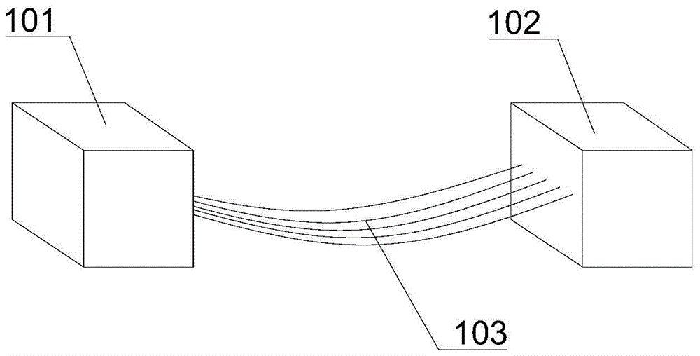
[0077] figure 1 It is an axonometric schematic diagram of the kinetic energy absorbing device provided by the first embodiment of the present invention; figure 1 As shown, the kinetic energy absorbing device ...


PUM


Abstract

The invention provides a kinetic energy absorption device, a kinetic energy buffering absorption device and a manufacturing technology of the kinetic energy absorption device, and relates to the field of buffering machines. The kinetic energy absorption device comprises a first fixing end, a second fixing end and strip-shaped cut-off portions. Any two adjacent strip-shaped cut-off portions are arranged in a spaced mode. The two ends of each strip-shaped cut-off portion are connected with the first fixing end and the second fixing end respectively. According to the kinetic energy absorption device, a decelerated object is made to lose energy, and the kinetic energy of the decelerated object is correspondingly decreased; meanwhile, according to the impulse principle, the kinetic energy of the decelerated object is decreased, the speed is correspondingly decreased, and then the impact force of the decelerated object is correspondingly decreased.

Description

technical field [0001] The invention relates to the field of cushioning machinery, in particular to a kinetic energy absorbing device, a kinetic energy buffering and absorbing device and a manufacturing process for the kinetic energy absorbing device. Background technique [0002] The energy possessed by an object due to its motion is called its kinetic energy. Its magnitude is defined as half the product of the object's mass times the square of its velocity. Therefore, for objects with the same mass, the greater their velocity, the greater their kinetic energy; for objects with the same velocity, their mass is greater, and their kinetic energy is greater. It can be seen that even an object with a very small mass will have a very high energy at a very high speed. [0003] On the one hand, we can use kinetic energy, such as nail guns, to give the internal nails a very high speed by using the nail gun, so that the nails have extremely high kinetic energy and can be pushed in...

Claims


Application Information

Patent Timeline
Patent Type & Authority Applications(China)
IPC IPC(8): F16F15/02
CPCF16F15/02
Inventor 梅光华谢紧东李铸坪
Owner 成都特戎新材料有限公司
Why Eureka
Try Eureka