Omni-directional naked eye 3D display device and working principle thereof

A display device, omnidirectional naked-eye technology, applied in optical components, optics, instruments, etc., can solve the problem of not being able to fully realize 360° omnidirectional 3D display, improve mechanical performance and service life, reduce air resistance, and expand availability. The effect of viewing angle

Active Publication Date: 2015-11-18
深圳秀蛋科技有限公司
View PDF4 Cites 11 Cited by
  • Summary
  • Abstract
  • Description
  • Claims
  • Application Information

AI Technical Summary

Problems solved by technology

[0004] The invention provides an omnidirectional naked-eye 3D display device and its working principle to overcome the disadvantage that the existing stereoscopic imaging device cannot fully realize 360° omnidirectional 3D display

Method used


Image

  • Omni-directional naked eye 3D display device and working principle thereof
  • Omni-directional naked eye 3D display device and working principle thereof
  • Omni-directional naked eye 3D display device and working principle thereof

Examples


Embodiment 1

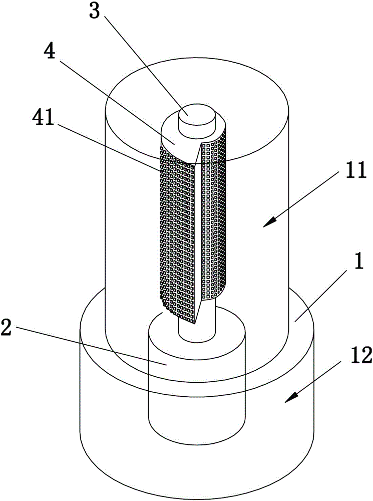
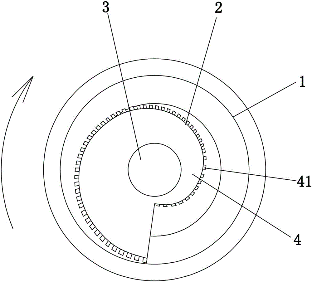
[0027] refer to figure 1 with figure 2 , an omnidirectional naked-eye 3D display device, comprising a housing 1, a rotating shaft 3, and a motor 2 for driving the rotating shaft 3 to rotate. The side wall of the rotating shaft 3 is provided with a plurality of uniformly distributed pixel light-emitting points 41, and these pixel light-emitting points 41 are provided by a dot-matrix curved display screen 4 arranged on the side wall of the rotating shaft 3 in a spiral shape. In the dot-matrix curved display screen 4 , the distances between the plurality of pixel light-emitting points 41 at the same height and the sidewall of the rotating shaft 3 are different, and are arranged in a spiral shape. When the motor 2 drives the rotating shaft 3 to rotate at a high speed, these pixel light-emitting points 41 form a cylindrical dot matrix screen with a depth of d around the rotating shaft 3, where d is the pixel light-emitting point 41 farthest from the rotating shaft 3 and the pixel...

Embodiment 2

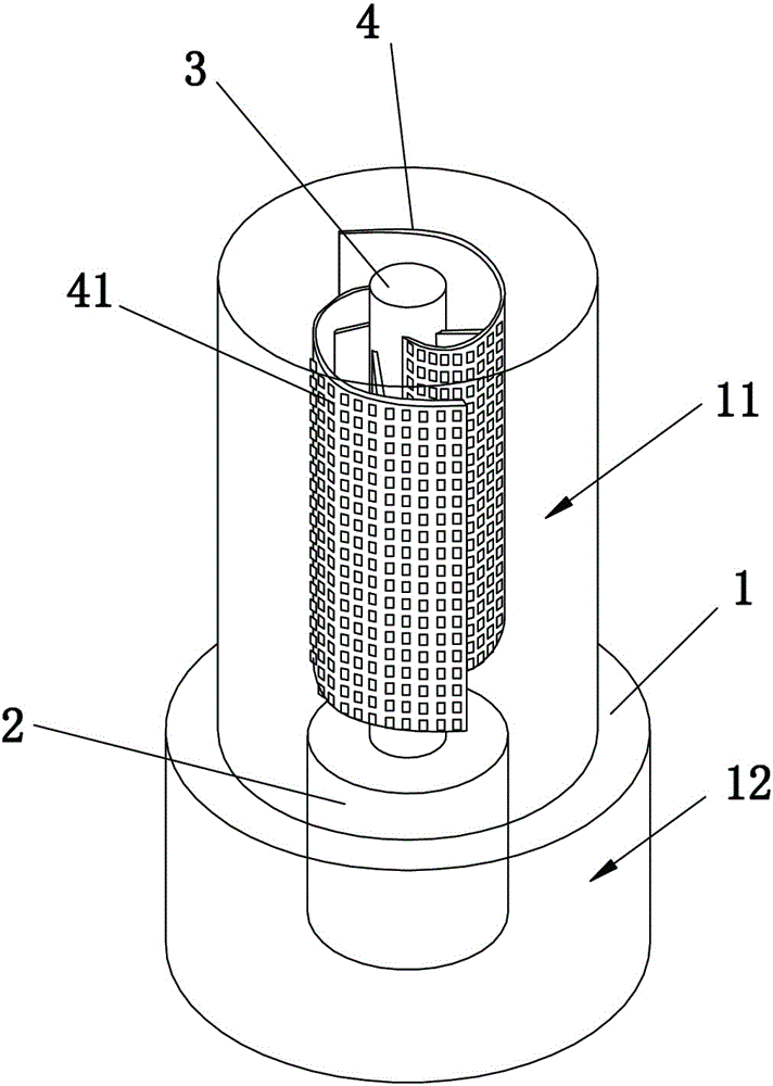
[0031] refer to image 3 with Figure 4 , an omnidirectional naked-eye 3D display device, comprising a housing 1, a rotating shaft 3, and a motor 2 for driving the rotating shaft 3 to rotate. The side wall of the rotating shaft 3 is provided with a plurality of uniformly distributed pixel light-emitting points 41, and these pixel light-emitting points 41 are provided by two dot-matrix curved display screens 4 uniformly arranged on the side wall of the rotating shaft in the arrangement of windmill blades. The distances between the plurality of pixel light-emitting points 41 at the same height of the dot-matrix curved display screen 4 and the sidewall of the rotating shaft 3 are different, and are arranged in a spiral shape. When the motor 2 drives the rotating shaft 3 to rotate at a high speed, these pixel light-emitting points 41 form a columnar light-emitting dot matrix with a certain depth around the rotating shaft 3 . When each pixel light-emitting point 41 emits light in...


PUM


Abstract

An omni-directional naked eye 3D display device and a working principle thereof relates to the field of equipment for generating the three-dimensional effect. The omni-directional naked eye 3D display device comprises a rotating shaft and a motor driving rotation of the rotating shaft. A side wall of the rotating shaft is provided with a plurality of pixel luminous points which are uniformly distributed. Distances between the pixel luminous points which are at the same height and arranged around the side wall of the rotating shaft and the center of the rotating shaft are different. The beneficial effects are that when the motor drives the rotating shaft to rotate at the high speed, the pixel luminous points of different extension lengths form a column lattice screen of a certain depth around the rotating shaft. When the pixel luminous points emit light in sequence, people can directly observe light emitted by the pixel luminous points at different distances, and a visual distance difference is formed, so that a good three-dimensional effect is formed, and the 360-degree omni-directional naked eye 3D display is achieved.

Description

technical field [0001] The invention relates to the field of equipment for producing stereoscopic effects, in particular to an omnidirectional naked-eye 3D display equipment and its working principle. Background technique [0002] With the development of science and technology, people's requirements for display imaging technology continue to increase. Traditional flat (two-dimensional) display can no longer meet people's requirements, and more and more people start to pay attention to three-dimensional (three-dimensional) imaging. Most of the current stereoscopic imaging devices are composed of upper substrate components, polarizing plates and films, lower glass components, [0003] Composed of LCD or LED, drive circuit unit, backlight module and other accessories, the structure is complicated, the cost is high, and it is difficult to popularize. Moreover, the existing stereoscopic imaging devices cannot fully realize 360° omnidirectional 3D display. Contents of the invent...

Claims


Application Information

Patent Timeline
Patent Type & Authority Applications(China)
IPC IPC(8): G02B27/22
CPCG02B30/54
Inventor 林水龙
Owner 深圳秀蛋科技有限公司
Why Eureka
Try Eureka