Operating rod special for anti-bird instrument live-line installation

A bird repellent and operating lever technology, applied in the direction of overhead lines/cable equipment, etc., can solve the problems of operators safely burying major hidden dangers and high working intensity, and achieves improved continuous stability, improved service level, reduced processing difficulty and The effect of assembly and debugging difficulty

Active Publication Date: 2015-11-18
STATE GRID SHANDONG ELECTRIC POWER +1
View PDF12 Cites 8 Cited by
  • Summary
  • Abstract
  • Description
  • Claims
  • Application Information

AI Technical Summary

Problems solved by technology

Because the power distribution line is long, if the bird repellent is installed according to the current installation method of the bird repellent, and at the same time limited by the small number of personnel, multiple power outages are required. On the one hand, it will bring a lot of inconvenience to electricity customers, on the other hand , During the installation process, it is necessary to climb to the top of the tower to operate. The whole process is not only intensive but also poses a major hidden danger to the safety of operators.

Method used


Image

  • Operating rod special for anti-bird instrument live-line installation
  • Operating rod special for anti-bird instrument live-line installation
  • Operating rod special for anti-bird instrument live-line installation

Examples


Embodiment approach 1

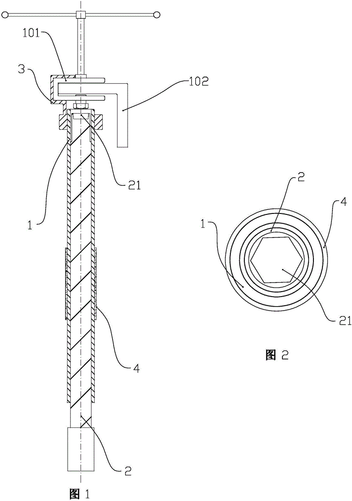
[0031] The special operating rod for live installation of the bird repellent includes a sleeve rod 1, a rotating rod 2 and a fixed part 3. The sleeve rod 1 is provided with an axial cavity, and threads are arranged on the inner wall of the cavity. An anti-slip rubber sleeve 4 is provided at the middle and lower part of the outer wall of the sleeve rod 1 . The rotating rod 2 is coaxially assembled in the axial inner cavity of the sleeve rod 1 through a threaded connection structure, and the axial length of the rotating rod 2 is greater than the axial length of the sleeve rod 1 .

[0032] An axial counterbore 21 is arranged on the upper end surface of the rotary rod 2, at least the lower part of the inner cavity of the counterbore 21 is formed as a hexagonal cavity. Such as figure 1 , figure 2As shown, the axial length of the counterbore 21 on the upper end surface of the rotary rod 2 is 0.8 times the axial thickness of the bolt and nut on the U-shaped seat 101 of the bird r...

Embodiment approach 2

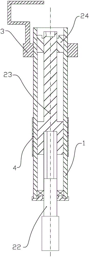
[0036] It differs from Embodiment 1 in that the structure of the rotating rod 2 and the assembly form between the rotating rod 2 and the sleeve rod 1 are changed. Specifically:

[0037] The rotary rod 2 includes a driving rod 22 and a lifting rod 23 , and the counterbore 21 is arranged on an upper surface of the lifting rod 23 . The lower end surface of the lifting rod 23 is provided with an axial threaded blind hole. The upper end of the driving rod 22 is matched with the threaded blind hole at the lower end of the elevating rod 23 . The drive rod 22 cooperates with the lower port of the sleeve rod 1 through a bearing. A screw sleeve 24 coaxial with the sleeve rod 1 is fixedly arranged on the upper end of the cavity of the sleeve rod 1 . The outer wall of the upper end of the lifting rod 23 cooperates with the screw sleeve 24, and the cooperation form between the lifting rod 23 and the screw sleeve 24 adopts a ball screw nut structure. The outer diameter of the lower end ...

Embodiment approach 3

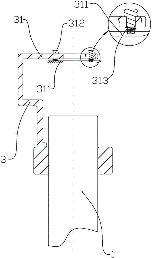
[0040] Compared with the first two installation methods, the improvement mainly lies in the top plate 31 of the U-shaped bayonet on the clamping part of the fixing part 3 . Specifically:

[0041] The fixing part also includes a pressing plate 311 and a plurality of connecting bolts 312 . The right end of the top plate 31 of the U-shaped bayonet on the clamping part of the fixing part 3 extends rightward relative to the axis of the sleeve rod 1 .

[0042] In the middle of the top plate 31 , a notch extending left and right is provided from the right end of the top plate 31 .

[0043] On the top plate, a row of two through holes are respectively arranged on the front side and the rear side of the notch.

[0044] On the pressing plate 311, corresponding to the notch and the through hole on the top plate 31, corresponding notches and threaded holes are set, and the front and rear width of the notch on the pressing plate 311 is not less than that on the top plate 31. The front-t...


PUM


Abstract

An operating rod special for anti-bird instrument live-line installation comprises a sleeving rod, a rotation rod and a fixed part. The sleeving rod is provided with an axial cavity. The rotation rod is coaxially assembled in the axial inner cavity and is capable of moving up and down relative to the sleeving rod. The upper end surface of the rotation rod is provided with a counter bore. The lower part of an inner cavity of the counter bore is six-row-shaped. The fixed part comprises a sleeving ring and a clamping part. The sleeving ring is provided with an inner thread and is connected with the outer wall of the upper end of the sleeving rod. The clamping part of the fixed part is provided with a U-shaped bayonet, a base plate of the U-shaped bayonet is arranged at the left side of the outer wall of the sleeving rod, and the right end of a top plate of the U-shaped bayonet extends to the part above the upper end surface of the sleeving rod. The operating rod is capable of realizing anti-bird instrument live-line installation and fundamentally solving the problem that a plurality of power failures of a power line are caused due to power-off installation of an anti-bird instrument, so that the frequency and time of power failures of the power distribution line are reduced, the continuous stability of power supplying is improved, the service level of power supplying is improved, the labor intensity of operators is reduced, and the operation safety is ensured.

Description

technical field [0001] The invention relates to the field of power transformation application equipment, in particular to a special operating lever for live installation of a bird repellent. Background technique [0002] Since the power supply lines are mostly located in the suburbs and are elevated, the duration of the power supply lines will be "harassed" by birds' nesting. According to statistics, the faults of power distribution lines caused by bird nesting have been on the rise in a straight line in recent years. The reason is related to the current indiscriminate logging and the continuous expansion of human activities. Birds nesting on power supply towers will seriously threaten the safe power supply of power distribution lines, so effective measures must be taken to stop them. At present, it is mainly to clean up the bird's nest after finding the bird's nest during line inspection, which is far from enough to realize the safety and reliability of the distribution li...

Claims


Application Information

Patent Timeline
IPC IPC(8): H02G1/02
Inventor 张友泉安鹏孙宝峰于光远
Owner STATE GRID SHANDONG ELECTRIC POWER
Why Eureka
Try Eureka