
CAN bus fault diagnosis method and system

A fault diagnosis system and CAN bus technology, applied in the field of CAN bus, can solve problems such as difficulty in analysis and processing, lack of communication fault diagnosis function, CAN bus cannot communicate normally, etc., and achieve the effect of automatic diagnosis

Active Publication Date: 2015-11-18
HUNAN SANY INTELLIGENT CONTROL EQUIP
View PDF6 Cites 10 Cited by
  • Summary
  • Abstract
  • Description
  • Claims
  • Application Information

AI Technical Summary

Problems solved by technology

Too many resistors connected to the CAN bus (more than 2), or too few (less than 2), or not connected will cause the CAN bus to fail to communicate normally
[0003] However, in the usual CAN communication equipment, there is no diagnostic function for communication faults, so once a fault occurs, it is difficult to analyze and deal with it, and professional technicians must be present to solve it

Method used


Image

  • CAN bus fault diagnosis method and system
  • CAN bus fault diagnosis method and system
  • CAN bus fault diagnosis method and system

Examples


Embodiment Construction

[0022] It should be pointed out that the description and sequence of specific structures in this section are only descriptions of specific embodiments, and should not be considered as limiting the protection scope of the present invention. In addition, the embodiments in this section and the features in the embodiments can be combined with each other under the condition of no conflict.

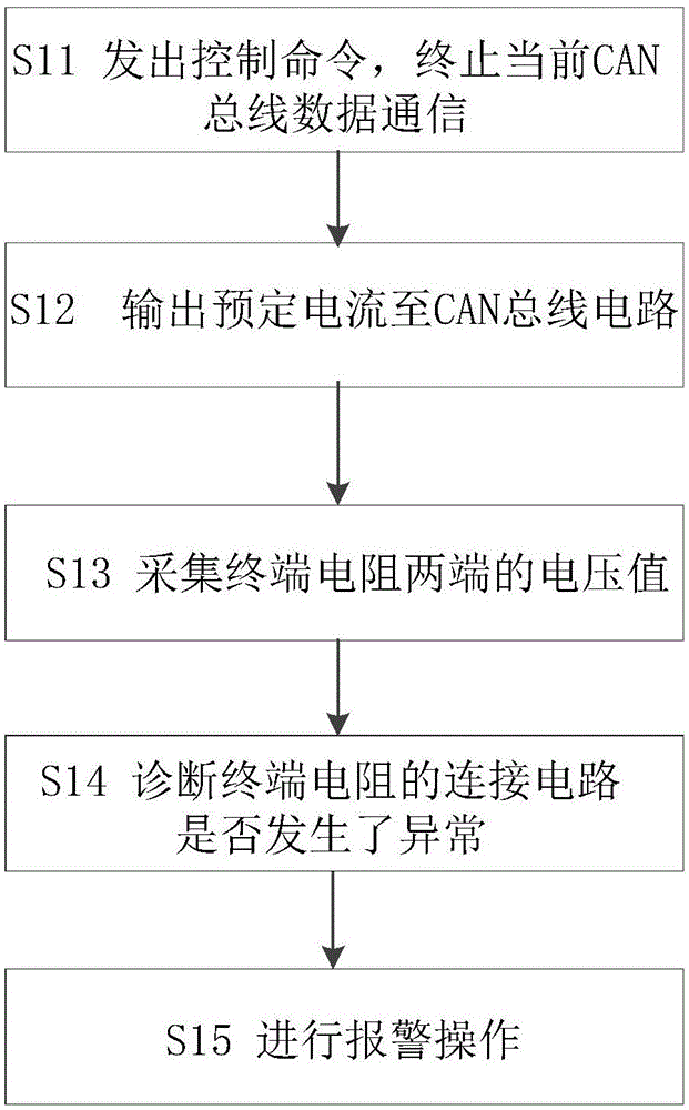
[0023] Please refer to figure 2 , the CAN bus fault diagnosis method of the embodiment of the present invention will be described in detail below with reference to the accompanying drawings.

[0024] Such as figure 2 Shown, the CAN bus fault diagnosis method of this embodiment can comprise the steps:

[0025] S11: The CAN master node issues a control command to terminate the current CAN bus data communication;

[0026] S12: The current source in the CAN master node outputs a predetermined current to the CAN bus circuit;

[0027] S13: the voltage measurement unit in the CAN master node co...


PUM


Abstract

The invention relates to a CAN bus fault diagnosis method and system. The method comprises the steps that A) a control command is emitted, and present CAN bus data communication is stopped; B) a pre-determined current is output to a CAN bus circuit; C) the voltage value at the two ends of a terminal resistor in the CAN bus circuit is collected; and D) when the voltage value is greater than a first or second preset threshold, a connected circuit of the terminal resistor is determined to be abnormal. The method and system can automatically diagnose faults of the terminal resistor.

Description

technical field [0001] The invention relates to the field of CAN bus, in particular to a CAN bus fault diagnosis method and system. Background technique [0002] In the operation of the controller system, it often encounters system operation errors due to communication failures. In CAN bus communication, communication abnormalities are usually caused by problems such as terminal resistance or high bus load rate. Such as figure 1 As shown, in a normal CAN bus connection, a resistor of about 120 ohms is connected to the terminals of the CAN bus to eliminate signal reflection in the bus cable. Too many resistors (more than 2), or too few (less than 2), or not connected to the CAN bus will cause the CAN bus to fail to communicate normally. [0003] However, in the usual CAN communication equipment, there is no diagnostic function for communication faults, so once a fault occurs, it is very difficult to analyze and deal with, and professional technicians must be present to sol...

Claims


Application Information

Patent Timeline
IPC IPC(8): H04L12/24H04L12/40
CPCH04L12/40169H04L41/06
Inventor 罗诗风陈祖亮谢秀芬
Owner HUNAN SANY INTELLIGENT CONTROL EQUIP
Learn More