Antenna switching system and method

An antenna switching and antenna technology, applied in diversity/multi-antenna systems, radio transmission systems, antennas, etc., can solve the problem that the number of channels is limited by the number of main antennas, and achieve the effect of increasing the number of channels

Active Publication Date: 2015-11-18
HUAWEI DEVICE CO LTD
View PDF5 Cites 15 Cited by
  • Summary
  • Abstract
  • Description
  • Claims
  • Application Information

AI Technical Summary

Problems solved by technology

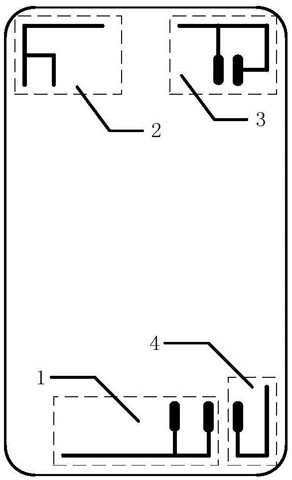
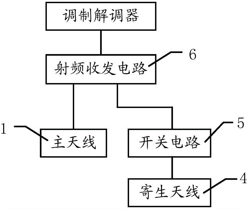
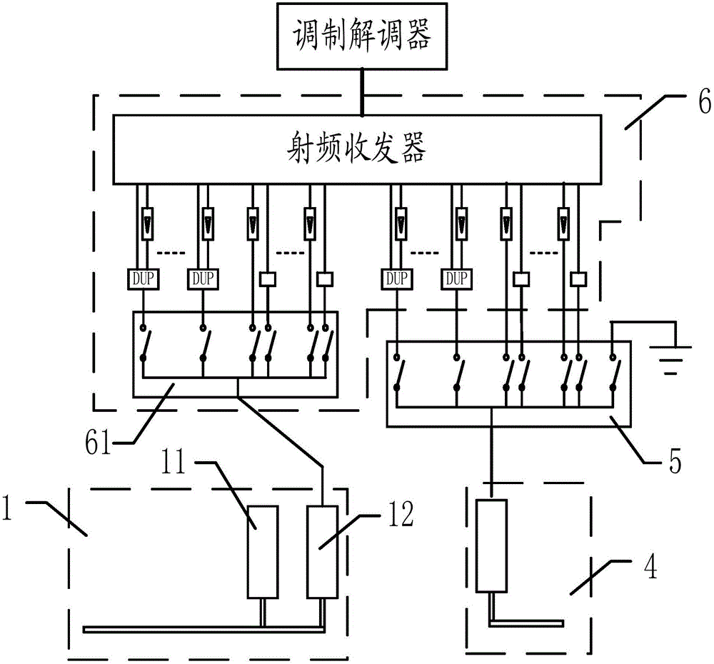
[0004] The purpose of the embodiments of the present invention is to provide an antenna switching system and method to solve the problem in the prior art that the number of channels for receiving or transmitting radio frequency signals is limited by the number of main antennas

Method used


Image

  • Antenna switching system and method
  • Antenna switching system and method
  • Antenna switching system and method

Examples


Embodiment Construction

[0053] In order to make the object, technical solution and advantages of the present invention clearer, the present invention will be further described in detail below in conjunction with the accompanying drawings and embodiments. It should be understood that the specific embodiments described here are only used to explain the present invention, not to limit the present invention.

[0054] In the embodiment of the present invention, "the first duplexer", "the first radio frequency power amplifier", "the first code division system receiving end", "the first code division system transmitting end", "the first time division system transmitting end" The "first" contained in "end", "the first time division system receiving end" and "the first surface acoustic filter" are all references and are only used for distinction. "The second duplexer", "the second radio frequency power amplifier", "the second code division system receiver", "the second code division system transmitter", "the ...


PUM


Abstract

The present invention applies to the field of mobile terminals, and provides an antenna switching system and method. The antenna switching system comprises a radio frequency transceiver circuit, a main antenna and a parasitic antenna. The main antenna is connected to the radio frequency transceiver circuit. The antenna switching system also comprises a switch circuit, used for connecting the parasitic antenna to the radio frequency transceiver circuit, when the parasitic antenna is being used to receive or transmit a radio frequency signal. If the parasitic antenna is connected to the ground, the parasitic antenna may be used for spreading. In addition, when carrier aggregation is required, the parasitic antenna is connected to the radio frequency transceiver circuit, becoming an independent receiving or transmitting antenna. In this way, no new antennae are added, only a main antenna and a parasitic antenna included in an existing mobile terminal are used, and the effect of increasing the number of paths for receiving or transmitting a radio frequency signal is achieved.

Description

technical field [0001] The invention belongs to the field of mobile terminals, and in particular relates to an antenna switching system and method. Background technique [0002] For a mobile terminal (for example, a mobile phone), when it is necessary to increase the uplink rate and / or the downlink rate, it can be realized by increasing the bandwidth. The bandwidth increase can be implemented by carrier aggregation (CarrierAggregation, CA), which specifically includes the following two types: the first type, carrier aggregation within a frequency band; the second type, carrier aggregation in different frequency bands. For the first scheme of increasing the bandwidth, a main antenna can be used to receive radio frequency signals, and different I / Q (in-phase / quadrature) demodulation can be used for the received radio frequency signals. As for the second solution for increasing bandwidth, in the prior art, due to the fact that the radio frequency resources actually used in mob...

Claims


Application Information

Patent Timeline
Patent Type & Authority Applications(China)
IPC IPC(8): H04B7/06H04B7/08
CPCH01Q1/24H04B7/0602H04B7/0825H01Q1/243H01Q9/42H01Q21/28H01Q5/378H03F3/24H04W4/06H01Q3/24H01Q1/48H04B1/44H04B7/0805H04B2001/0408H04L5/14
Inventor 徐求良杨丽萍张昌峰陈志君
Owner HUAWEI DEVICE CO LTD
Why Eureka
Try Eureka