Battery charging and discharging test method and system based on energy storage PCS (Power Conversion System) + BMS (Battery Management System)

A charge-discharge test, charge-discharge technology, applied in the direction of measuring electricity, measuring devices, measuring electrical variables, etc., can solve the problems of high cost, low production capacity, and many testing equipment, and achieve small investment, reduced investment, and strong scalability Effect

Inactive Publication Date: 2019-05-07
长园深瑞继保自动化有限公司 +2
View PDF8 Cites 8 Cited by
  • Summary
  • Abstract
  • Description
  • Claims
  • Application Information

AI Technical Summary

Problems solved by technology

This battery detection solution requires the outsourcing of a complete set of equipment or the targeted development of related battery charging and discharging equipment. The investment is large and the scalability is poor. A bidirectional DCDC branch can only complete the charging and discharging detection and capacity calibration of one battery pack at the same time.
[0004] The disadvantages of battery charging and discharging solutions currently on the market mainly include: 1. High cost. Energy storage manufacturers need to purchase a complete set of battery charging and discharging testing equipment, or develop bidirectional power supplies, bidirectional DCDC converters and supporting PC software. Two ways to invest are larger
2. Poor scalability. The current battery charge and discharge detection equipment on the market is generally single-channel or dual-channel

Method used


Image

  • Battery charging and discharging test method and system based on energy storage PCS (Power Conversion System) + BMS (Battery Management System)
  • Battery charging and discharging test method and system based on energy storage PCS (Power Conversion System) + BMS (Battery Management System)

Examples


Embodiment Construction

[0032] Below in conjunction with embodiment the present invention is further described.

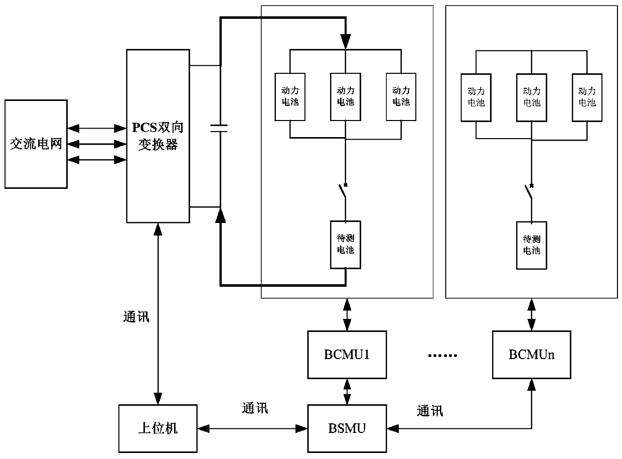
[0033] A battery charge and discharge test method based on energy storage PCS+BMS, comprising the following steps:

[0034] S1. Build the public DC bus required for battery charging and discharging through the energy storage PCS;

[0035] S2. When the battery is charging, the energy storage PCS extracts energy from the grid side. When the battery is discharging, the energy storage PCS feeds back the power on the DC bus to the grid;

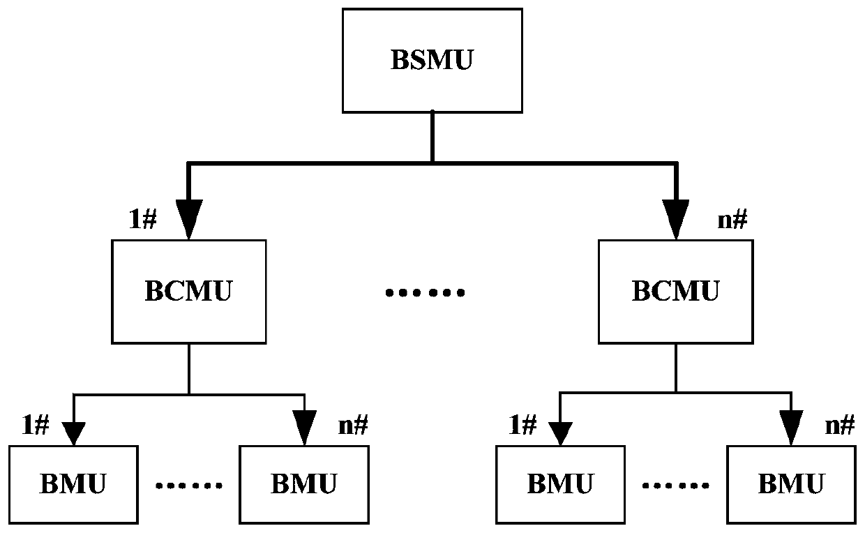
[0036] S3. The battery to be tested is connected to the DC bus, and each group of batteries to be tested is equipped with a set of BCMU. The BCMU is used to monitor the state of the battery to be tested, and to control the input and removal of the battery to be tested in the charging and discharging circuit;

[0037] S4. All the battery branches to be tested summarize the battery charge and discharge information through the BSMU, complete the battery charge ...


PUM


Abstract

The invention discloses a battery charging and discharging test method and a system based on energy storage PCS (Power Conversion System) + BMS (Battery Management System). The method comprises the following steps: constructing a common DC bus required for charging and discharging a battery through an energy storage PCS; when the battery is being charged, extracting energy from the network side bythe energy storage PCS, and when the battery is discharged, feeding the power quantity on the DC bus back to a power grid by the energy storage PCS; hooking the battery to be tested to the DC bus, wherein each group of batteries to be tested is equipped with a set of BCMU (Battery Control Management Unit) for monitoring the state of the battery to be tested and controlling inputting in and removal from the charge and discharge circuit of the battery to be tested; and summarizing the battery charge and discharge information, completing a protection and control strategy for the battery chargingand discharging, and uploading relevant information to a host computer by all battery branches to be tested through the BSMU. The investment of the battery charging and discharging test method and the system based on the energy storage PCS + BMS is low and the expandability thereof is strong, and the invention can be used for battery testing by using PCS and BMS of an engineering project. After the battery testing is completed, the PCS and the BMS can enter the warehouse together with the battery, thereby reducing the investment of fixed assets.

Description

technical field [0001] The invention relates to the technical field of battery charging and discharging testing. Background technique [0002] Energy storage technology, especially electrochemical energy storage technology, has developed rapidly in recent years due to its characteristics of reactive power compensation and improving the stability of power systems. Energy storage batteries are the core and foundation of electrochemical energy storage systems, and the quality and stability of energy storage batteries are the basis for the stability of electrochemical energy storage systems. [0003] Before the energy storage battery enters the warehouse, the energy storage battery needs to be carefully tested, including the detection of internal resistance, the detection of sampling accuracy, and the charge and discharge test of the battery (capacity calibration), etc. For the charge and discharge test of the energy storage battery, it is necessary to use the battery charge an...

Claims


Application Information

Patent Timeline
IPC IPC(8): G01R31/385G01R31/387
Inventor 徐成斌陈锐张壹飞周国琦丁凯
Owner 长园深瑞继保自动化有限公司
Why Eureka
Try Eureka