Mounting device for spring in oil pump

A mounting device and spring mounting technology, applied in metal processing, metal processing equipment, manufacturing tools, etc., can solve problems such as low assembly efficiency, inadequate spring compression, slippage, etc., achieve stable transfer positions, ensure assembly accuracy, and improve The effect of assembly efficiency

Active Publication Date: 2015-11-25
NINGBO SHENGLONG AUTOMOTIVE POWERTRAIN SYSTEM CO LTD
View PDF6 Cites 19 Cited by
  • Summary
  • Abstract
  • Description
  • Claims
  • Application Information

AI Technical Summary

Problems solved by technology

[0005] 1) Since when the spring is transferred to the spring installation groove of the oil pump, the receiving seat is only placed on the end face of the oil pump housing without any connection structure, so it is easy to remove the receiving seat when the spring is transferred. The phenomenon of slipping occurs, which causes the spring to not be smoothly transferred to the spring installation groove on the oil pump, which in turn leads to low assembly efficiency;
[0006] 2) In addition, after the spring is compressed by the pressure block, both the adjustment bolt and the pressure block are subjected to the reaction force of the spring, and when the spring is knocked into the spring installation groove on the oil pump, the vibration generated by the knock will make the adjustment bolt in the spring Under the action of the reaction force, the receiving seat is unscrewed, so that the spring is not compressed enough before it enters the spring installation groove on the oil pump. In other words, the compression of the spring does not reach the preset length. As a result, the spring cannot fully enter the spring installation groove of the oil pump, and the adjusting bolt has to be screwed in again until the compression of the spring reaches the preset span, which affects the assembly efficiency

Method used


Image

  • Mounting device for spring in oil pump
  • Mounting device for spring in oil pump
  • Mounting device for spring in oil pump

Examples


Embodiment Construction

[0027] The present invention will be described in further detail below in conjunction with the accompanying drawings and specific embodiments.

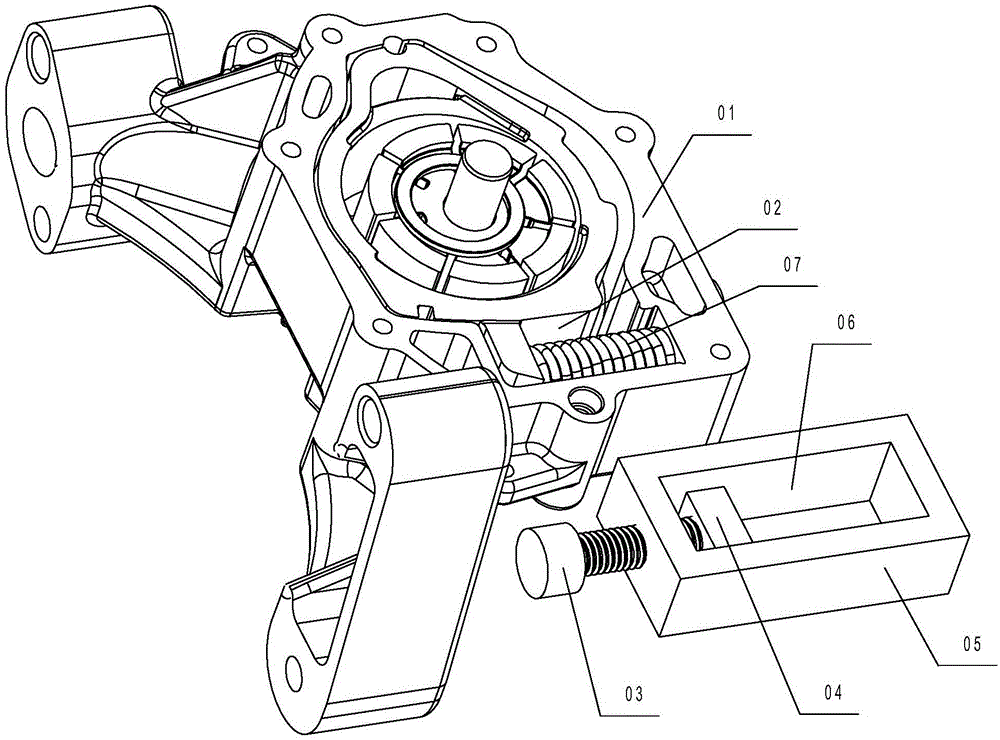
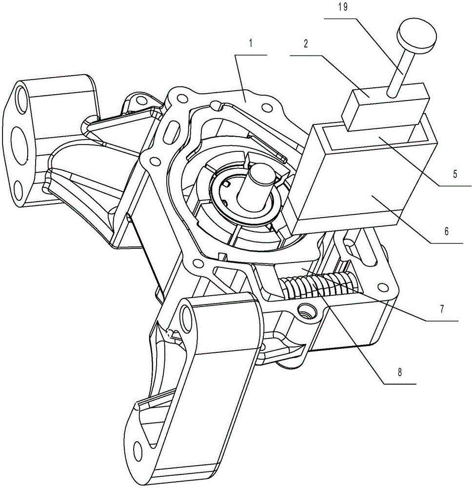
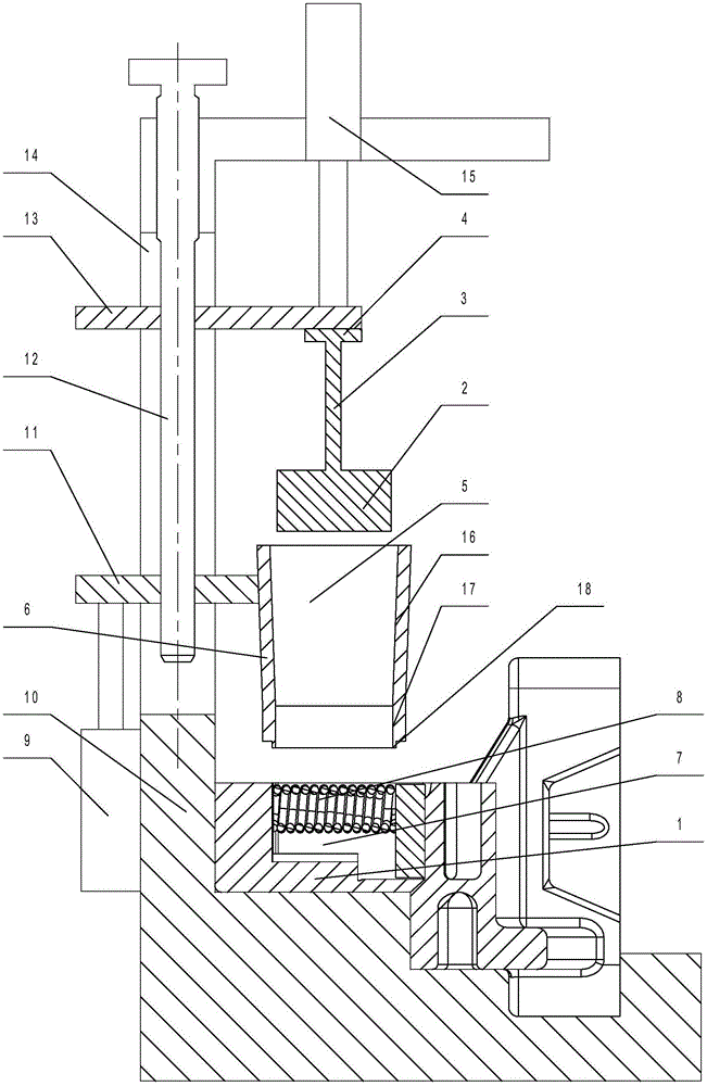
[0028] Depend on figure 2 and image 3 It can be seen from the structural diagram of the installation device of the spring in the oil pump of the present invention that it includes a press-in seat 6 and a press block 2 for pressing the spring 8 into the spring installation groove 7 on the oil pump 1, and the press-in seat 6 has a Can accommodate and compress the press-in through hole 5 of the spring 8, the cross section of the press-in through-hole 5 is a rectangular hole, and the upper section of the press-in through-hole 5 is a slope 16 at both ends of the spring 8 in the length direction. The lower end of the press-fit through hole 5 is located directly above the spring mounting groove 7, and the distance between the side walls at both ends decreases gradually from top to bottom. The upper end of the pressing block 2 is provided...


PUM


Abstract

The invention discloses a mounting device for a spring in an oil pump. The device comprises a press-in seat (6), and a pressing block (2) for pressing the spring (8) into a spring mounting groove (7) in the oil pump (1); a press-in through hole (5) for storing and compressing the spring (8) is formed in the press-in seat (6); the cross section of the press-in through hole (5) is shaped like a rectangular hole; the sidewalls of two ends of the upper section of the press-in through hole (5), in the length direction of the spring (8), are bevels (16); the lower end of the press-in through hole (5) is positioned right above the spring mounting groove (7), and the space between the sidewalls of two ends of the press-in through hole is reduced from top to bottom; a driving structure for pressing in is arranged at the upper end of the pressing block (2). According to the device adopting the structure above, the position of the spring is fixed relative to the oil pump during transferring, so that the phenomena of position deviating and inaccurate positioning can be avoided, the spring can be mounted conveniently, and as a result, the assembling efficiency can be greatly improved.

Description

technical field [0001] The invention relates to the technical field of moulds, in particular to a spring installation device in an oil pump. Background technique [0002] When the automobile engine is working, each moving part acts on another part with a certain force, and high-speed relative motion occurs. With relative motion, friction will inevitably occur on the surface of the parts, thereby accelerating wear. Therefore, in order to reduce wear and tear, reduce friction resistance and prolong service life, there must be lubrication system parts on the engine. The main components of the lubrication system are various equipment such as an oil pump. The function of the oil pump is to increase the oil to a certain pressure and then forcefully send it to the moving surface of each part of the engine. It generally includes a pump cover and a pump body. It is connected with the pump body by screws, and the pump body is equipped with an inner rotor, an outer rotor, a spring, a ...

Claims


Application Information

Patent Timeline
Patent Type & Authority Applications(China)
IPC IPC(8): B23P19/04
CPCB23P19/048
Inventor 邹娟罗玉龙周培良项鑫
Owner NINGBO SHENGLONG AUTOMOTIVE POWERTRAIN SYSTEM CO LTD
Why Eureka
Try Eureka