
Labor-saving clean-type glass cutting machine

A cutting machine and cleaning technology, applied in glass cutting devices, glass manufacturing equipment, stone processing tools, etc., can solve the problems of inability to guarantee the quality of glass processing, difficult to clean, and inefficient glass cutting process

Active Publication Date: 2015-11-25
苏州市灵通玻璃制品有限公司
View PDF5 Cites 8 Cited by
  • Summary
  • Abstract
  • Description
  • Claims
  • Application Information

AI Technical Summary

Problems solved by technology

[0002] The cutting machine is used for the division and cutting of sheets in various industries. It does not need any molds, and then directly cuts the product. As we all know, glass also needs to be cut. Glass cutting machine refers to special A processing machine for glass processing and blanking. Because the glass just produced in some factories is too large, the existing cutting machines for glass have various problems and cannot efficiently process glass. In the cutting process, the work of the workers is also extremely laborious, which makes it impossible to guarantee the processing quality of the glass; and when the cutting work is performed, the cut glass residues are everywhere, which is not only difficult to clean, but also very easy to hurt people.

Method used


Image

  • Labor-saving clean-type glass cutting machine
  • Labor-saving clean-type glass cutting machine

Examples


Embodiment Construction

[0014] Specific embodiments of the present invention will be further described in detail below.

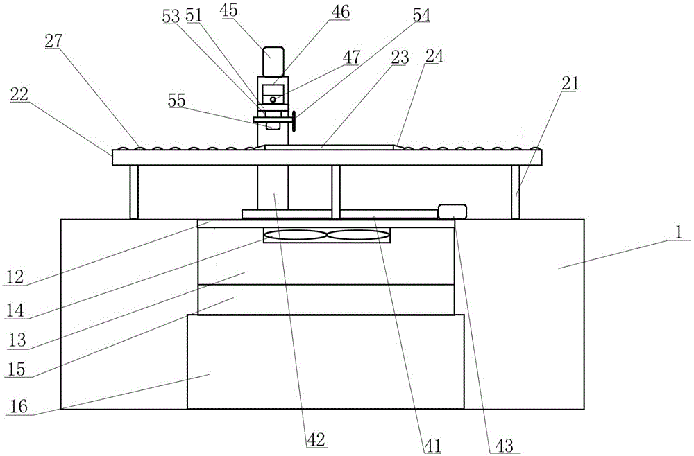
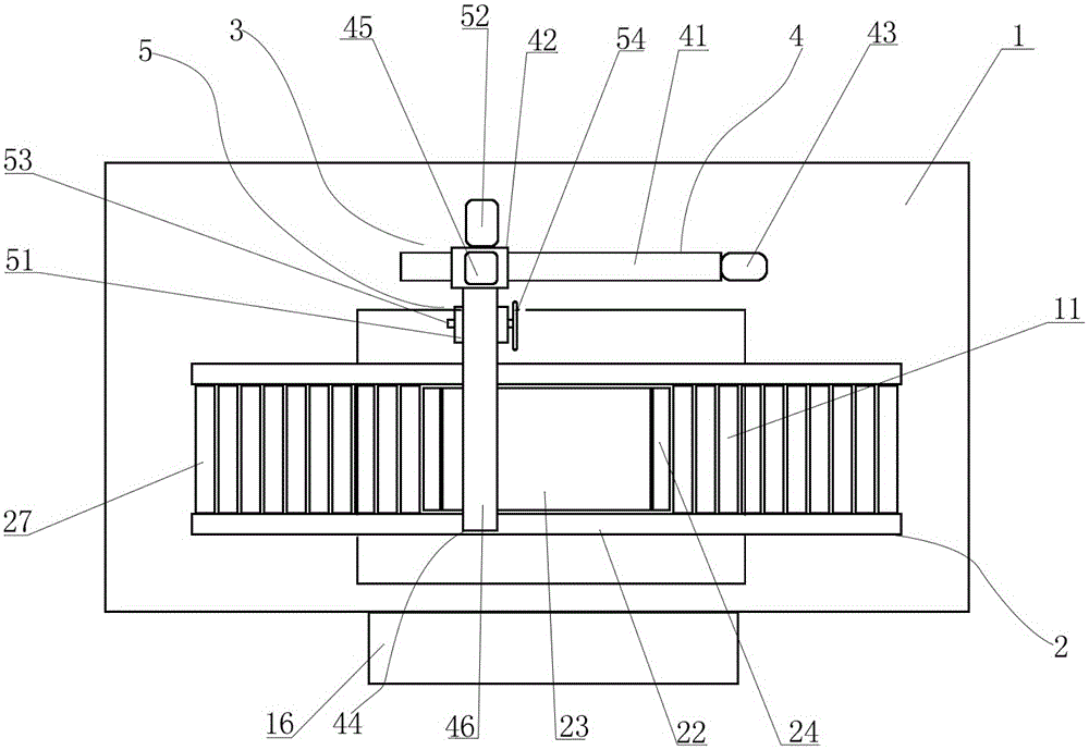
[0015] Such as figure 1 with figure 2 As shown, a labor-saving cleaning glass cutting machine of the present invention includes a frame 1, which is characterized in that: the frame 1 is provided with a carrying device 2, and one side of the carrying device 2 is provided with a cutting device 3 for cutting The device 3 includes a mechanical arm assembly 4 arranged on the frame 1 and a cutting assembly 5 arranged on the mechanical arm assembly 4. The carrying device 2 includes a plurality of vertical bars 21 arranged on the frame 1. The vertical bars 21 are arranged as Two rows, the top of the vertical bar 21 is respectively provided with two horizontal plates 22 in parallel, the middle part of the horizontal plate 22 is provided with a support plate 23 for placing workpieces, the support plate 23 is connected to the two horizontal plates 22, and the two sides of the support plate...


PUM


Abstract

The invention discloses a labor-saving clean-type glass cutting machine. The glass cutting machine comprises a machine frame, wherein a bearing device is arranged on the machine frame; a cutting device is arranged on one side of the bearing device; the cutting device comprises a mechanism arm assembly arranged on the machine frame, and a cutting assembly arranged on the mechanism arm assembly; the bearing device comprises a plurality of vertical rods arranged on the machine frame in two rows; two transverse plates are arranged in parallel at the tops of the vertical rods respectively; a supporting plate for allowing a workpiece to be placed is arranged in the middles of the transverse plates; a plurality of roller cylinders are isometrically arranged on each of two sides of the supporting plate; two ends of each roller cylinder are respectively connected with the two transverse plates; the roller cylinders can freely roll between the transverse plates; openings are respectively formed in two sides at the lower part of the bearing device, of the top of the machine frame; one metal filter screen is arranged in each opening; one collecting cylinder communicated with each opening is arranged under the corresponding opening; one negative-pressure fan is arranged in each collecting cylinder; one ramp is formed in one side of each collecting cylinder; one collecting box is arranged at the lower part of one side of each ramp; each collecting box is arranged on one side edge of the machine frame.

Description

technical field [0001] The invention relates to a glass cutting device, in particular to a glass cutting machine. Background technique [0002] The cutting machine is used for the division and cutting of sheets in various industries. It does not need any molds, and then directly cuts the product. As we all know, glass also needs to be cut. Glass cutting machine refers to special A processing machine for glass processing and blanking. Because the glass just produced in some factories is too large, the existing cutting machines for glass have various problems and cannot efficiently process glass. In the cutting process, the work of the workers is also extremely laborious, so that the processing quality of the glass cannot be guaranteed; and when the cutting work is performed, the cut glass residues are everywhere, which is not only difficult to clean, but also very easy to hurt people. Contents of the invention [0003] In order to overcome the above problems, the present...

Claims


Application Information

Patent Timeline
IPC IPC(8): B28D1/24B28D7/02C03B33/00
Inventor 陆志文
Owner 苏州市灵通玻璃制品有限公司
Learn More