Chip removal type anti-overflowing nozzle

An anti-overflow and nozzle cap technology is applied in the field of injection molding machine parts to achieve the effect of improving stability

Inactive Publication Date: 2015-11-25
林勇
View PDF3 Cites 1 Cited by
  • Summary
  • Abstract
  • Description
  • Claims
  • Application Information

AI Technical Summary

Problems solved by technology

In order to ensure the smooth complet...

Method used


Image

  • Chip removal type anti-overflowing nozzle
  • Chip removal type anti-overflowing nozzle
  • Chip removal type anti-overflowing nozzle

Examples


specific Embodiment approach

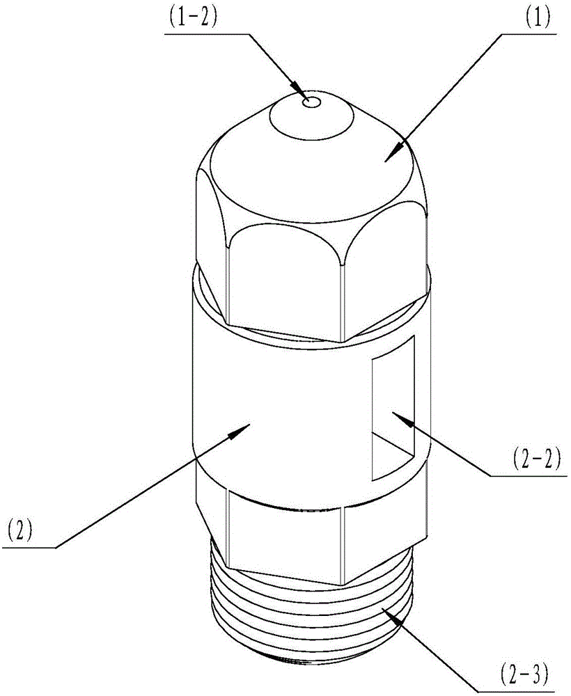
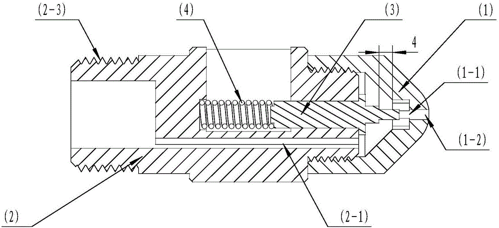
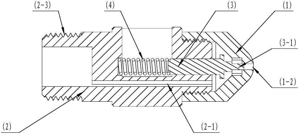
[0014] DETAILED DESCRIPTION OF THE PREFERRED EMBODIMENTS The chip removal type anti-overflow nozzle includes a nozzle cap (1), a nozzle body (2), a valve core (3) and a spring (4) as the main components. Its characteristics: during injection molding, the hydraulic device pushes the screw forward, forming a high-pressure glue melting area in the originally closed nozzle cap (1), and the high-pressure melting glue acts on the force surface (3-2) of the valve core (3). Then, a thrust is generated to compress the spring (4) to move the valve core (3) in the direction of the spring (4) until the limiting surface (3-4) of the valve core (3) is in contact with the nozzle body (2). The blocking column (3-1) of the valve core (3) is completely withdrawn from the injection channel (1-1) of the nozzle cap (1), such as figure 2 At this time, the molten glue is injected into the cavity of the mold through the injection channel (2-1), injection channel (1-3) and injection channel (1-1) of ...


PUM


Abstract

The invention discloses a chip removal type anti-overflowing nozzle. The chip removal type anti-overflowing nozzle comprises the main components including a nozzle cap, a nozzle body, a valve element and a spring. The chip removal type anti-overflowing nozzle is characterized in that a screw is pushed by a hydraulic device to advance during injection molding, an injection molding high-pressure molten plastic area is formed in the nozzle cap which is originally sealed, high-pressure molten plastic acts on the stress surface of the valve element, pushing force is generated and compresses the spring so that the valve element can move towards the spring till the limiting surface of the valve element is attached to the nozzle body, a blocking column of the valve element retreats from an injection molding channel of the nozzle cap completely at the moment, the molten plastic is injected into a cavity of a mold through the injection molding channel of the nozzle body at the moment till injection is completed, then the hydraulic device drives the screw to retreat, pressure in the high-pressure molten plastic area in the nozzle cap is released, the blocking column of the valve element is inserted into the injection molding channel again under the action of the elastic force of the spring, and the injection molding channel is blocked, so that molten plastic cannot overflow from the injection molding channel. In this way, a product can be produced smoothly.

Description

technical field [0001] The invention relates to a part of an injection molding machine, in particular to a chip discharge type anti-overflow nozzle. Background technique [0002] At present, the injection nozzle is an important part of the injection head in the injection molding machine. Usually, during injection molding, after the barrel is heated, the plastic particles are put into the barrel from the inlet, and the plastic particles are sent through the rotation of the screw in the injection head. To the side of the screw head, the heating device makes the plastic particles melt continuously, and then pushes the screw through the hydraulic device, and injects the molten plastic into the cavity of the mold through the nozzle to complete the injection molding action of the plastic machine. However, during the melting process, some plastics overflow from the nozzle by themselves, which will stick to the mold, causing inconvenience to mold production, and even causing product...

Claims


Application Information

Patent Timeline
IPC IPC(8): B29C45/23
CPCB29C45/231
Inventor 不公告发明人
Owner 林勇
Why Eureka
Try Eureka