
Shell assembly clamp

A technology for assembling fixtures and shells, which is applied in the field of fixtures, and can solve problems such as uneven bonding force between transparent panels and frames, uneven pressing force between transparent panels and frames, and weak assembly structures of transparent panels and frames

Active Publication Date: 2015-11-25
GUANGDONG OPPO MOBILE TELECOMM CORP LTD
View PDF9 Cites 2 Cited by
  • Summary
  • Abstract
  • Description
  • Claims
  • Application Information

AI Technical Summary

Problems solved by technology

[0002] At present, the assembly process of the mobile phone shell is manually assembled. For example, in the process of assembling the frame and the transparent panel, first spray the hot-melt adhesive strip on the inside of the frame, and then press the transparent panel into the frame. After the adhesive strip is cured, Realize the assembly and fixation of the transparent panel and the frame. However, in this method, since the transparent panel is pressed on the frame, it is usually pressed manually, so that the pressing force on the transparent panel and the frame is not uniform, and it is easy to cause adhesion between the transparent panel and the frame. The relay is uneven, making the assembly structure between the transparent panel and the frame weak
Therefore, there is currently no device that can guarantee a stable pressing force during the assembly process of the mobile phone case.

Method used


Image

  • Shell assembly clamp
  • Shell assembly clamp

Examples


Embodiment Construction

[0018] The following will clearly and completely describe the technical solutions in the embodiments of the present invention in conjunction with the drawings in the embodiments of the present invention. Apparently, the described embodiments are some, not all, embodiments of the present invention. Based on the implementation manners in the present invention, all other implementation manners obtained by persons of ordinary skill in the art without making creative efforts shall fall within the protection scope of the present invention.

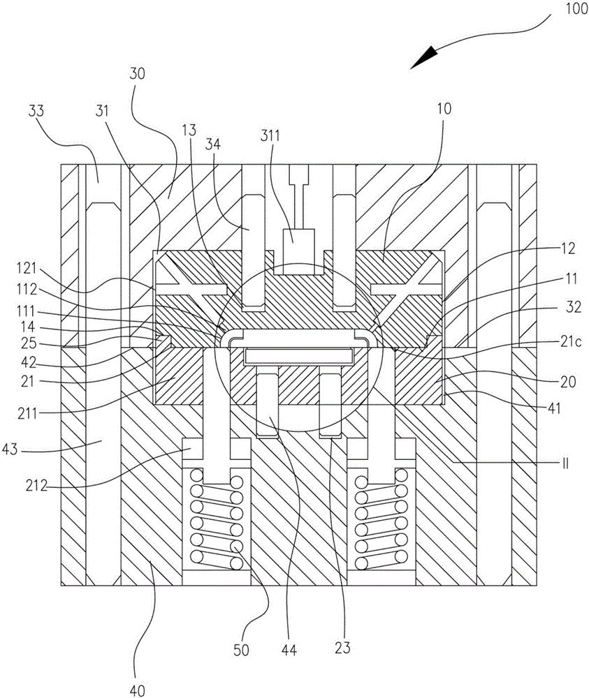
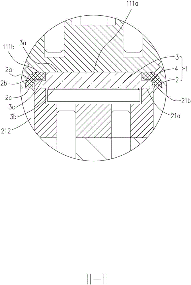
[0019] Please also refer to figure 1 and figure 2 , the housing assembly jig 100 provided by the embodiment of the present invention, the housing assembly jig 100 is used for assembling the frame 2 and the transparent panel 3 of the housing assembly 1 , as well as the glue 4 provided on the periphery of the transparent panel 3 . The housing assembly 1 includes a frame 2 and a transparent panel 3 , the frame 2 surrounds the periphery of the tr...


PUM


Abstract

The invention relates to a shell assembly clamp. The shell assembly clamp comprises an upper mold core and a lower mold core arranged in a sliding mode relative to the upper mold core. The upper mold core comprises an upper mold joint face and an upper mold side face surrounding the upper mold joint face. First suction holes are formed in the upper mold side face and used for being communicated with a negative-pressure pump. An accommodation space with an opening facing the lower mold core is formed in the upper mold joint face and used for accommodating a frame. A plurality of second suction holes are formed in the bottom of the accommodation space and are communicated with the first suction holes. The lower mold core comprises a lower mold joint face which is opposite to the upper mold joint face and used for fixing a transparent panel. A plurality of through holes are formed in the lower mold joint face, and a sliding rod is arranged in each through hole in a sliding mode. The sliding rods slide out of the through holes so as to be arranged on the periphery of the transparent panel to locate the transparent panel.

Description

technical field [0001] The invention relates to the field of clamps, in particular to a housing assembly clamp. Background technique [0002] At present, the assembly process of the mobile phone shell is manually assembled. For example, in the process of assembling the frame and the transparent panel, first spray the hot-melt adhesive strip on the inside of the frame, and then press the transparent panel into the frame. After the adhesive strip is cured, Realize the assembly and fixation of the transparent panel and the frame. However, in this method, since the transparent panel is pressed on the frame, it is usually pressed manually, so that the pressing force on the transparent panel and the frame is not uniform, and it is easy to cause adhesion between the transparent panel and the frame. The relay is uneven, making the assembled structure between the transparent panel and the frame weak. Therefore, there is currently no device that can guarantee a stable pressing force ...

Claims


Application Information

Patent Timeline
Patent Type & Authority Applications(China)
IPC IPC(8): B29C65/52
Inventor 唐义梅王晓辉许宇初刘兵陈伟李勇张伟廖新风孙毅邹宏胡志勤
Owner GUANGDONG OPPO MOBILE TELECOMM CORP LTD
Learn More