
Instant testing platform clip

A test bench and fixture technology, which is applied in the field of instantaneous test bench fixtures, can solve problems such as unreliable workpiece compression, influence test results, and different contact resistances, and achieve stable pressing force, correct test data, and reliable workpiece positioning.

Inactive Publication Date: 2007-12-19
上海亿盟电气自动化技术有限公司
View PDF0 Cites 1 Cited by
  • Summary
  • Abstract
  • Description
  • Claims
  • Application Information

AI Technical Summary

Problems solved by technology

[0004] Since the 4 groups of contacts are pulled by the same cylinder, the contact of each contact is pressed by the spring, so the contact resistance of each group of contacts will be different, which will affect the test results
[0005] Unreliable workpiece pressing due to contact claws pressing the workpiece

Method used


Image

  • Instant testing platform clip

Examples


Embodiment Construction

[0022] The present invention will be further described below in conjunction with accompanying drawing.

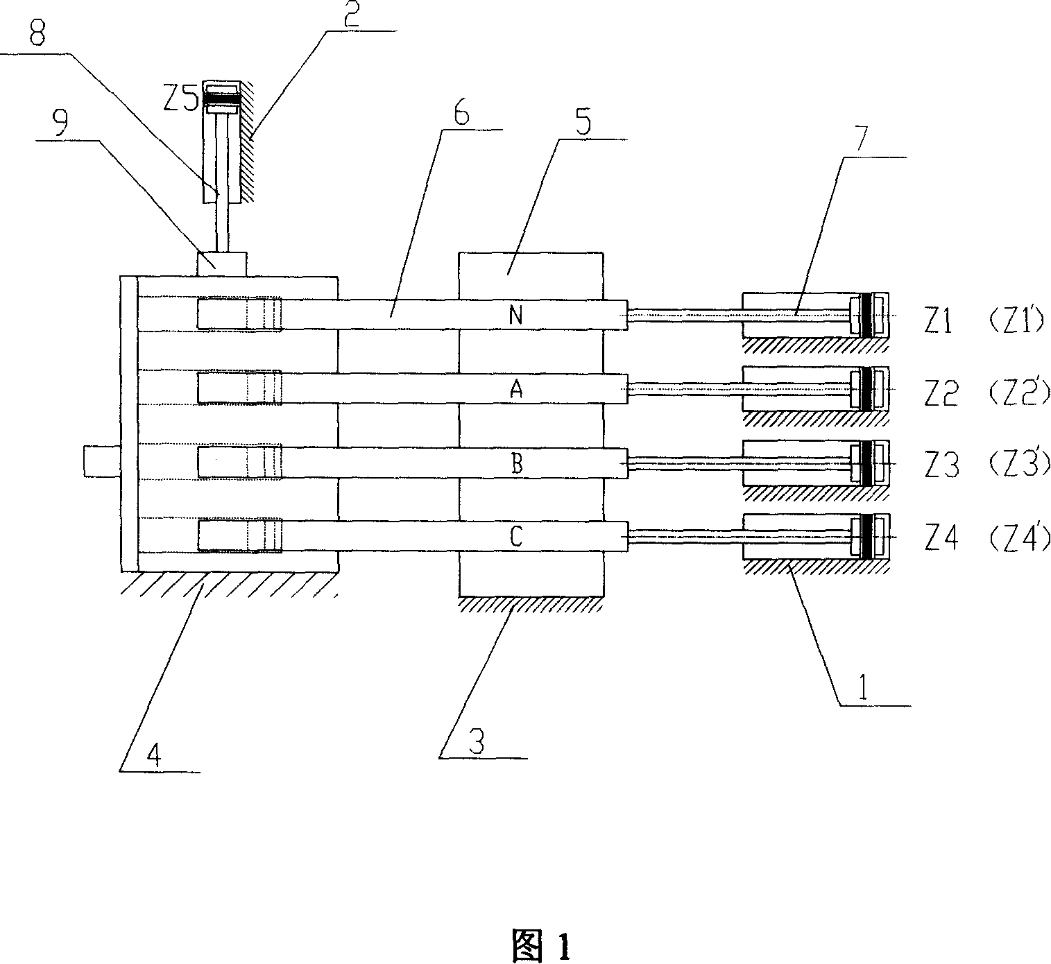
[0023] As shown in Figure 1, the instantaneous test bench fixture includes a fixture bracket, a guide rail body 5, at least two cylinders 7, four sets of contact claws 6, and a side pressure cylinder 8. The guide rail body 5, at least two cylinders 7, The four sets of contact claws 6 and the side pressure cylinders 8 are all arranged on the fixture bracket. The at least two cylinders 7 are connected to the four sets of contact claws 6 respectively, and the pressure blocks 9 are arranged on the side pressure cylinders 8 .

[0024] Described cylinder 7 is four, and these four cylinders 7 are respectively connected four groups of contact claws 6; Described fixture support comprises cylinder support one 1, cylinder support two 2, rail body support 3, workpiece support 4, described The cylinder support one 1, the guide rail body support 3, and the workpiece support 4 are arrange...


PUM


Abstract

A clamping fixture of instant test table is prepared as setting guide track, at least two air-cylinders, four sets of contact paws and side pressure air-cylinder on support frame of said clamping fixture; connecting said at least two air-cylinders separately to four sets of contact paws and setting press-block on said side pressure air-cylinder.

Description

technical field [0001] This invention relates to fixtures, and more particularly to transient test bench fixtures. Background technique [0002] Usually, the instantaneous test is carried out on the molded case circuit breaker. Generally, a cylinder is used to pull four sets of (N, A, B, C phase) contact claws, and then the contactor is switched to realize the single-phase calibration or serial calibration power-on test. This test has the following three problems: [0003] Due to the large current, a large current contactor is required for switching. [0004] Since the 4 groups of contacts are pulled by one cylinder, the contact of each contact is pressed by a spring, so the contact resistance of each group of contacts will be different, which will affect the test results. [0005] Since the workpiece is pressed with the contact claws, the workpiece is not reliably pressed. Contents of the invention [0006] The object of the present invention is to provide an instant t...

Claims


Application Information

Patent Timeline
Patent Type & Authority Applications(China)
IPC IPC(8): G01R1/02G01R31/327
Inventor 徐惠国尚晓冬
Owner 上海亿盟电气自动化技术有限公司
Learn More