Weather resistance take-up and pay-off device

A wire take-up and pay-off device and weather-resistant technology, which is applied in the field of weather-resistant wire take-up and pay-off devices, can solve problems such as breakage, bending and bending of weather-resistant wires, and increased labor intensity of workers.

Inactive Publication Date: 2015-11-25
国网山东五莲县供电公司 +1
0 Cites 0 Cited by

AI-Extracted Technical Summary

Problems solved by technology

[0002] When laying out the high-voltage wires, you can use the wire-releasing bracket to pay out the wires, but the thinner or lighter cables, such as 6 square meters or 16, 25, and 35 square meters of weather-resistant wires, have to be paid out manually, and the wires must be paid out at the same time. Straight...

Method used

[0017] The retractable inner roulette includes a retractable inner ring 32 sleeved outside the retractable shaft sleeve 31, and several inner rings are connected between the retractable inner ring 32 and the retractable shaft sleeve 31. Circle support bar 33, said structure is convenient to take-up and take-off carrying out, and production is simple, and material consumption is few, saves cost.
[0018] The clamping outer wheel disc includes a clamping outer ring 43...

Abstract

The invention discloses a weather resistance take-up and pay-off device. The weather resistance take-up and pay-off device comprises a base. The base is provided with a support. The two sides of the support are provided with supporting screws. The inner end side of each supporting screw is sleeved with a take-up and pay-off shaft sleeve. The inner end portion of each take-up and pay-off shaft sleeve is provided with a take-up and pay-off inner wheel disc. The take-up and pay-off shaft sleeves are sleeved with wire coil clamping mechanisms. The outer end side of each supporting screw is sleeved with a clamping shaft sleeve. A clamping outer wheel disc is arranged on each clamping shaft sleeve. Clamping nuts are further connected with the outer sides, on the supporting screws, of the clamping shaft sleeves in a threaded mode. Wheel discs of weather resistance lines are arranged on the wire coil clamping mechanisms in a sleeving mode, then the clamping shaft sleeves are arranged on the supporting screws in a sleeving mode, the clamping nuts are screwed up to enable the clamping outer wheel discs to clamp the wheel discs of the weather lines, and take-up and pay-off can be conducted. By means of the weather resistance take-up and pay-off device, take-up and pay-off of the weather resistance lines are facilitated, the quality of the weather resistance lines is guaranteed, the labor intensity of workers is lowered, and the efficiency of take-up and pay-off is improved as well.

Technology Topic

Weather resistanceEngineering +2

Image

  • Weather resistance take-up and pay-off device
  • Weather resistance take-up and pay-off device

Examples

  • Experimental program(1)

Example Embodiment

[0014] The present invention will be further explained below in conjunction with the drawings and embodiments. In the following detailed description, only certain exemplary embodiments of the present invention are described by way of illustration. Needless to say, those of ordinary skill in the art can realize that the described embodiments can be modified in various ways without departing from the spirit and scope of the present invention. Therefore, the drawings and description are illustrative in nature, and are not used to limit the protection scope of the claims.
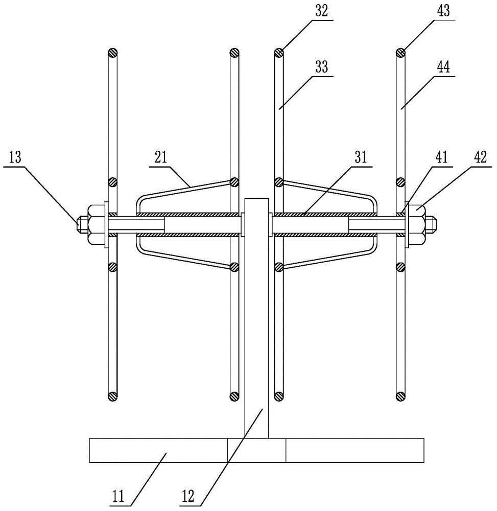
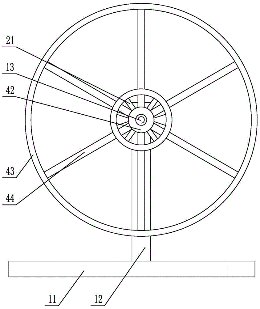
[0015] Such as figure 1 with figure 2 As shown, the weather-resistant wire take-up and unwinding device includes a base 11 on which a bracket 12 is provided. Both sides of the bracket 12 are respectively provided with support screws 13, and the inner end of each support screw 13 is A retractable shaft sleeve 31 is sleeved, the inner end of the retractable shaft sleeve 31 is provided with a retractable inner wheel, and the retractable shaft sleeve 31 is sleeved with a wire reel clamping mechanism, and each of the support screws 13 is sleeved on the outer end side of a clamping sleeve 41, the clamping sleeve 41 is provided with a clamping outer wheel disc, the outside of the clamping sleeve 41 is also threaded on the support screw 13 is connected with a clamp Tighten the nut 42. The retractable shaft sleeve 31 and the retractable inner reel are sleeved on the supporting screw 13, the weather-resistant wire reel is sleeved on the wire reel clamping mechanism, and then the clamping sleeve 41 and the clamping outer roulette are sleeved on the supporting screw 13, and the clamping nut 42 is tightened so that the clamping outer roulette clamps the roulette of the weatherproof line. At this time, only one person in the front can pull the weather-resistant line gently, and at the same time, it can straighten the weather-resistant line to avoid damage and breakage of the weather-resistant line, and to ensure the safety of the weather-resistant line during set-up. When taking up the thread, turn the retractable inner roulette in the opposite direction to take up the thread. It is also possible for two people to take up and pay off at the same time, which greatly improves the speed of retracting and releasing, and guarantees the progress of work. This embodiment facilitates the take-up and pay-off of the weather-resistant line, ensures the quality of the weather-resistant line, reduces the labor intensity of workers, and also improves the efficiency of the line.
[0016] The spool chuck mechanism includes a plurality of spool chucking rods 21 whose inner ends are connected to the retractable inner reel. The outer ends of the spool chucking rods 21 are inclined and gathered toward the retractable sleeve 31. Connected to the outer end of the retractable sleeve 31. Since the retractable shaft sleeve 31 at the outer end of the spool chuck rod 21 is inclined and gathered, it is easy to cover the roulette of the weather-resistant line on the spool chuck rod 21, and push the roulette of the weather-resistant line toward the center. When the inner end of the wire reel clamping rod 21 is tightened gradually, it is convenient to fix the roulette of the weather-resistant wire.
[0017] The retractable inner wheel includes a retractable inner ring 32 sleeved outside the retractable shaft sleeve 31, and a plurality of inner ring support rods are connected between the retractable inner ring 32 and the retractable shaft sleeve 31 33. The above-mentioned structure is convenient for the take-up and pay-off, and the production is simple, the material is small, and the cost is saved.
[0018] The clamping outer wheel includes a clamping outer ring 43 sheathed outside the clamping sleeve 41, and a plurality of outer ring support rods 44 are connected between the clamping outer ring 43 and the clamping sleeve 41 , The above structure is convenient to install the roulette that clamps the weather resistance line, and the production is simple, the material is small, and the cost is saved.
[0019] The base 11 is arranged in a "T" shape, and the above-mentioned structure has good stability and is easy to produce.
[0020] The above shows and describes the basic principles, main features and advantages of the present invention. Those skilled in the industry should understand that the present invention is not limited by the foregoing embodiments. The foregoing embodiments and descriptions only illustrate the principles of the present invention. Without departing from the spirit and scope of the present invention, the present invention may have Various changes and improvements, these changes and improvements fall within the scope of the claimed invention. The scope of protection claimed by the present invention is defined by the appended claims and their equivalents.

PUM

no PUM

Description & Claims & Application Information

We can also present the details of the Description, Claims and Application information to help users get a comprehensive understanding of the technical details of the patent, such as background art, summary of invention, brief description of drawings, description of embodiments, and other original content. On the other hand, users can also determine the specific scope of protection of the technology through the list of claims; as well as understand the changes in the life cycle of the technology with the presentation of the patent timeline. Login to view more.
Why Eureka
Try Eureka