Speed reducer of motor reversely-arranged bidirectional output piling machine

A two-way output, reducer technology, applied in the direction of electromechanical devices, electrical components, mechanical equipment, etc., can solve the problems of large tipping moment, high cost, unstable center of gravity of pile driver, etc., to reduce tipping moment, pile foundation The effect of high quality and reduced chance of tipping accidents

Inactive Publication Date: 2015-11-25
吴小杰
View PDF14 Cites 0 Cited by
  • Summary
  • Abstract
  • Description
  • Claims
  • Application Information

AI Technical Summary

Problems solved by technology

[0005] (1) Since the large gear of the outer power head D is connected to the large-diameter (SWSD3618 drilling diameter is 1.5 meters) casing, the overall size will be large, heavy, expensive and difficult to install;
[0006] (2) Since the upper and lower ends of the box of the outer power head D are supported by large-diameter bushings, not only the lubrication state of the bearings is not good, oil leakage is easy, but also the manufacturing cost is high and the installation and maintenance are difficult
[0011] The problems of background technology (2) to (5) are: the top-mounted dual motors make the center of gravity of the pile driver high, the overturning moment is large, the pile driver has a hidden danger of instability, and the pile driver will overturn.
[0014] (2) On September 07, 2006, at the construction site in front of the Hechuan Building at No. 2010 Yishan Road, Shanghai, a pile driver suddenly overturned, not only crushing the factory building on the side of the road, but also causing an old man to be injured. So it will suddenly tip over, mainly because the soil is too loose and the center of gravity of the pile driver is unstable;
[0017] (1) Due to the harsh working conditions at the construction site, most of the operators do not have maintenance equipment and skills. When a fault occurs, it is difficult to remove the heavy motor and reducer, so it is difficult to repair and maintain;
[0018] (2) Due to the harsh working conditions at the construction site, the cap of the motor is difficult to waterproof and dustproof

Method used


Image

  • Speed reducer of motor reversely-arranged bidirectional output piling machine
  • Speed reducer of motor reversely-arranged bidirectional output piling machine

Examples


Embodiment Construction

[0034] The present invention is described in detail below in conjunction with accompanying drawing:

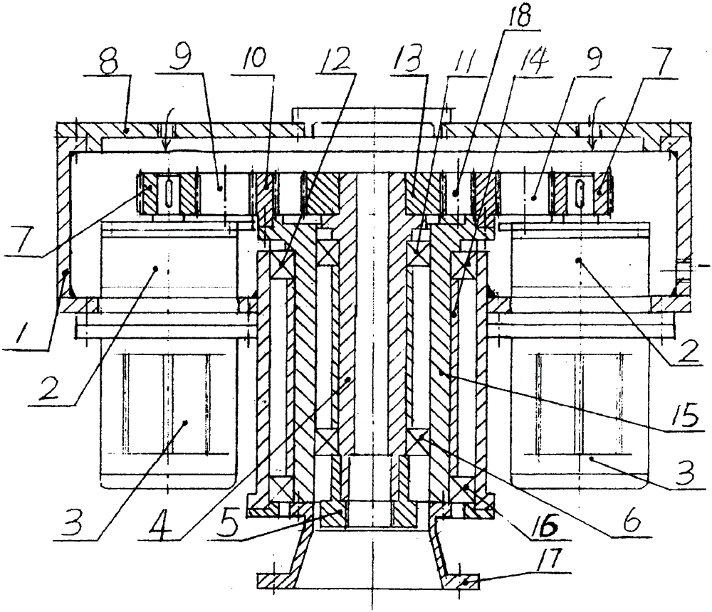
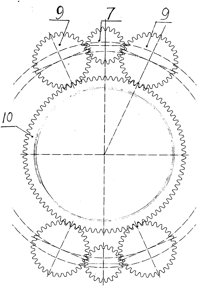
[0035] refer to figure 1 and 2 . A motor inverted two-way output pile driver reducer, including a box body 1, two motors 3, a cover plate 8 and a gear transmission part placed in the box body 1, characterized in that:

[0036] The shaft extension ends of the two motors 3 are connected to the double cycloid reducer 2;

[0037] The two motors 3 are connected upside down under the box body 1, and the double cycloid reducer 2 is placed in the box body 1. The carrying capacity of the double cycloid reducer is comparable to that of the general double fulcrum cycloid model. 1 to 2 models are improved, and the motor 3 is symmetrical on both sides of the output center;

[0038] The gear transmission part is a transmission part of two sets of fixed-axis shunt structures, including an external meshing deceleration part and an internal meshing quasi-planetary speed-up part. The extern...


PUM


Abstract

The invention relates to the technical field of piling machine speed reducing, and discloses a speed reducer of a motor reversely-arranged bidirectional output piling machine. The speed reducer comprises a box body, two motors, a cover plate and a gear transmission part. The speed reducer is characterized in that the two motors are connected with double-cycloid speed reducer parts, and are connected with the lower part of the box body in a reversely arranged manner; the double-cycloid speed reducer parts are arranged in the box body; the gear transmission part comprises an outer gearing speed reducing part and an inner gearing quasi-planet speed increasing part; the outer gearing speed reducing part comprises driving wheels, diversion gears and an outer gear of a center tooth ring; the inner gearing quasi-planet speed increasing part comprises an inner tooth ring part of the center tooth ring, a quasi-planet wheel and a center gear; the diversion gears and a mandrel of the quasi-planet wheel are fixed in the cover plate; the center tooth ring is connected with an outer sleeve; the outer sleeve is supported in the cover plate by a first bearing and a second bearing; the center gear is connected with an inner cylinder; and the inner cylinder is supported in an inner hole of the outer sleeve by a third bearing and a fourth bearing. The speed reducer has the benefits that the lumpish motors and the speed reducer part are easy to dismount, so that the service and maintenance are convenient; a tilting moment of the piling machine is reduced, so that the probability of tipping accidents is reduced; and water prevention and dust prevention of the motors are facilitated.

Description

【Technical field】 [0001] The invention relates to the technical field of double-motor-driven pile driver deceleration, and relates to a motor-inverted bidirectional output pile driver reducer. 【Background technique】 [0002] (1) The invention patent of China Sunward Intelligent Equipment Co., Ltd. "Separate-drive casing auger and its construction method" (ZL200610138353.3) discloses the following technical characteristics of deceleration drive: [0003] (a) Between the inner power head C and the outer power head D: the former is at the high end, the latter is at the bottom, and the two power heads are separated; [0004] (b) The driving devices in the inner and outer power heads both adopt dual-motor two-stage NGW planetary reduction, and the output pinion drives the middle gear to do work at the same time. Its main problems are: [0005] (1) Since the large gear of the outer power head D is connected to the casing with a large diameter (SWSD3618 drilling diameter is 1.5 m...

Claims


Application Information

Patent Timeline
Patent Type & Authority Applications(China)
IPC IPC(8): F16H1/36H02K7/116
CPCF16H1/36H02K7/116
Inventor 吴声震
Owner 吴小杰
Why Eureka
Try Eureka