
Street lamp device capable of rotating and moving

A technology for street lamps and street lamp poles, which is applied to lighting devices, fixed lighting devices, lighting auxiliary devices, etc., can solve the problems of short circuit, shorten the service life of lamp sockets, and shorten the service life, so as to increase the service life and reduce the short circuit phenomenon. , to ensure the effect of sealing performance

Inactive Publication Date: 2015-11-25
HUZHOU MINGRI LIGHTING TECH
View PDF6 Cites 2 Cited by
  • Summary
  • Abstract
  • Description
  • Claims
  • Application Information

AI Technical Summary

Problems solved by technology

However, since the street lights are installed at a higher position, and the range of people's activities is limited, it is often necessary to use a climbing vehicle to maintain the street lights, which is likely to cause road congestion and a relatively high risk factor
At the same time, because the position of the lamp holder is fixed, when encountering some typhoon weather, the lamp holder will often bear a lot of wind force, which will shorten the service life of the lamp holder in the long run
Due to the fixed lamp holders of existing street lamps, lamp holder resources cannot be arranged flexibly. For example, when holding large-scale events, the organizers often need to bring their own lamps because there is not enough light.
Due to the poor sealing of the existing movable street lamp device, the interior of the street lamp pole is wet, which is easy to cause a short circuit
Therefore, in the existing technology, there are problems such as inconvenient street lamp maintenance, high risk, short service life, inability to arrange light resources flexibly and reasonably, and poor sealing.

Method used


Image

  • Street lamp device capable of rotating and moving
  • Street lamp device capable of rotating and moving
  • Street lamp device capable of rotating and moving

Examples


Embodiment Construction

[0017] The present invention will be further described below in conjunction with the accompanying drawings and embodiments, but not as a basis for limiting the present invention.

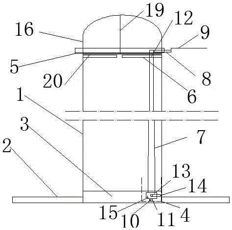
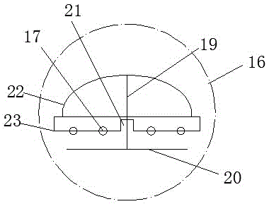
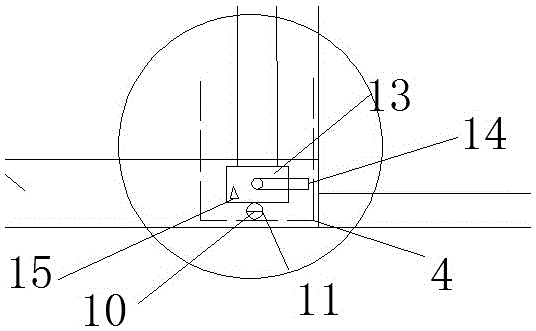
[0018] Example. A street lamp device capable of rotating and moving, constituted as figure 1 , figure 2 , image 3 , Figure 5 and Figure 6 As shown, including a street light pole 1 whose interior is hollow, the bottom of the street light pole 1 is connected with a base 2, and the inner wall of the street light pole 1 is provided with a circle of sliding track 3, and the sliding track 3 and the base 2 are located on the same plane, and the sliding track 3 is provided with hydraulic pressure. Device 4; a fixed disk 5 is connected to the top of the street light pole 1, and a rotating head 16 is connected to the fixed disk 5, and a card seat 6 is arranged on the inner wall of the street light pole 1 under the fixed disk 5; the rotating head 16 includes an oval sealing Head 22, the botto...


PUM


Abstract

The invention discloses a street lamp device capable of rotating and moving. The device comprises a hollow street lamp post (1), wherein a base (2) is connected to the bottom part of the street lamp post (1); a circle of slide rails (3) on which a hydraulic device (4) is arranged is arranged on the inner wall of the street lamp post (1); a fixed circular plate (5), which is connected with a rotating seal head (16), is connected to the top part of the street lamp post (1); a clamping seat (6) is arranged on the inner wall of the street lamp post (1) below the fixed circular plate (5); the rotating seal head (16) comprises an elliptic seal head (22) of which the bottom part is connected with a fixed seat (23); a plurality of ball positioning holes (17) and a plurality of balls (18) are correspondingly uniformly formed in and arranged on the contact surfaces of the fixed seat (23) and the fixed circular plate (5). The device has the characteristics of being convenient to repair, high in safety, long in service life, capable of flexibly and reasonably distributing the light, and high in sealing performance.

Description

technical field [0001] The invention relates to a lamp, in particular to a rotatable and movable street lamp device. Background technique [0002] At present, with the development of lighting technology, various lamps and lanterns appear. Street lamps are installed at higher positions because they need to illuminate a wider range. However, since the street lamps are installed at a higher position and the range of people's activities is limited, it is often necessary to use a climbing vehicle to maintain the street lamps, which is likely to cause road congestion and a relatively high risk factor. At the same time, since the position of the lamp holder is fixed, when some typhoon weather is encountered, the lamp holder will often bear a large wind force, which will shorten the service life of the lamp holder in the long run. Because the lamp sockets of existing street lamps are fixed, lamp socket resources cannot be arranged flexibly. For example, when large-scale events ...

Claims


Application Information

Patent Timeline
Patent Type & Authority Applications(China)
IPC IPC(8): F21S8/08F21V21/14F21W131/103
CPCF21S8/085F21V21/14F21W2131/103
Inventor 张会明
Owner HUZHOU MINGRI LIGHTING TECH
Learn More