A lining installation process of an industrial furnace

An installation process and an industrial furnace technology, applied in lining repair and other directions, can solve the problems of low cotton packing density, many hammering times, and many processes, and achieve the effect of guaranteed packing density, simple and clear process, and safety and reliability

Active Publication Date: 2017-05-10
HENAN TIANLI THERMOTECHNICAL EQUIP CO LTD
View PDF5 Cites 0 Cited by
  • Summary
  • Abstract
  • Description
  • Claims
  • Application Information

AI Technical Summary

Problems solved by technology

The current transmission processing technology is: use cotton blocks with anchors to wear on the stainless steel bolts welded on the inner side of the furnace wall, and tighten the nuts. The disadvantages are: the cost of purchasing cotton blocks with anchors is high, many tools are used, and the efficiency is low. , The operation is cumbersome, the process is many, the number of thumping is many, the vibration dust is more, the packing density is low, the heat insulation effect is poor, the customer is not satisfied, the construction personnel have a poor operating environment, which affects their health

Method used


Image

  • A lining installation process of an industrial furnace

Examples


Embodiment 1

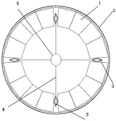
[0014] A furnace lining installation process for an industrial furnace, which includes the following steps: ① place the cube-shaped cotton blocks 1 close to the inner side 2 of the furnace wall, and insert a jack 3 when there are about five cotton blocks in each layer; Arrange the cotton blocks in the circle close to the furnace wall according to the arrangement in step 1, start the jack, and press the two ends of the jack to squeeze the cotton blocks on both sides respectively; Insert the cotton block, then start the adjacent jack to continue to squeeze, fill in the cotton blocks in each gap position in turn, and squeeze the cotton block from the gap in the last gap position, or use an auxiliary Tools, such as a pressing plate, are used to press the cotton block tightly, and a cutter can also be used to cut the cotton block, which is convenient for use; the jacks described are diamond jacks; each diamond jack is connected with the hand ring 5 by a steel wire stay rope 4 .

Embodiment 2

[0016] A furnace lining installation process for an industrial furnace, which includes the following steps: ① place the cube-shaped cotton blocks close to the furnace wall, and insert a jack when there are about seven cotton blocks in each layer; ② put the inner side of the furnace wall close to the furnace wall Arrange the cotton blocks according to the arrangement method in step 1, start the jack, and press the two ends of the jack to squeeze the cotton blocks on both sides; Then start the adjacent jack and continue to squeeze, and fill in the cotton blocks in each gap position in turn, and squeeze the cotton block from the gap in the last gap position. You can also use auxiliary tools, such as a pressing plate. Said that the cotton block is tightly plugged and pressed in, and a cutter can also be used to cut the cotton block, which is convenient for use; the jacks described are rhombus jacks; each rhombus jack is connected with the hand-held ring by a steel wire pull rope. ...


PUM


Abstract

A furnace lining installation process for an industrial furnace includes the following steps that firstly, cuboid cotton blocks are arranged near the inner side of a furnace wall and a jack is inserted every 5 to 7 cotton blocks in each layer; secondly, the cotton blocks are arranged in a circle, close to the furnace wall, of the inner side of the furnace wall according to the arrangement mode of the first step, the jacks are started, and the two ends of each jack squeeze the cotton blocks on the two sides respectively; and thirdly, the jacks in the jacking positions are taken out sequentially, the cotton blocks are sequentially placed in the empty positions, the adjacent jacks are started again for squeezing the cotton blocks continuously, the cotton blocks are sequentially placed in gaps, and the corresponding cotton block is plugged in the last gap tightly in a squeezed manner. By the adoption of the furnace lining installation process, the work procedure is simple, easy to learn and operate and low in installation cost. The cotton blocks are free of metal fasteners, no bolt is used for fixing, the conductive problem is avoided, and safety is reliable.

Description

[0001] Technical field: [0002] The invention relates to the processing of industrial furnaces, in particular to the furnace lining installation process of industrial furnaces. [0003] Background technique: [0004] The lining installation of industrial furnaces is a relatively common processing procedure in this field. The thermal insulation construction of various pit furnaces, vertical kilns and chimney inner walls with cotton lining is the most common construction in this field. The current transmission processing technology is: use cotton blocks with anchors to wear on the stainless steel bolts welded on the inner side of the furnace wall, and tighten the nuts. The disadvantages are: the cost of purchasing cotton blocks with anchors is high, many tools are used, and the efficiency is low. , The operation is cumbersome, the process is many, the number of thumping is high, there is a lot of vibration dust, the packing density is low, the heat insulation effect is poor, the...

Claims


Application Information

Patent Timeline
Patent Type & Authority Patents(China)
IPC IPC(8): F27D1/16
Inventor 李明科李振元王振广
Owner HENAN TIANLI THERMOTECHNICAL EQUIP CO LTD
Why Eureka
Try Eureka