
A Realization Method of 3D Space Positioning Based on RFID Middleware

A technology of three-dimensional space and realization method, which is applied in the field of RFID, positioning middleware, and three-dimensional space positioning algorithm, can solve the problems of inability to meet the three-dimensional space indoor positioning requirements, high cost of readers, and harsh use conditions, etc., to shorten the development cycle, The effect of masking differences and reducing estimation errors

Active Publication Date: 2019-04-09
SOUTH CHINA UNIV OF TECH
View PDF5 Cites 0 Cited by
  • Summary
  • Abstract
  • Description
  • Claims
  • Application Information

AI Technical Summary

Problems solved by technology

A LANDMARC (LocAtioN iDentification based on dynamic Active RfidCalibration) location awareness system has been widely studied. The basic idea of ​​the LANDMARC algorithm is to arrange a series of reference tags and readers. Each reader has multiple signal strength levels. According to the signal strength level , using the k-nearest neighbor method to estimate the target label coordinates, however, the LANDMARC algorithm can only provide coarse-grained positioning information, and cannot meet the indoor positioning requirements in 3D space
Some studies have proposed an accurate RFID three-dimensional space positioning method. The basic idea is to use the Nelder-Mead nonlinear optimization scheme to minimize the error function, but this algorithm requires a lot of readers and costs a lot.
At the same time, some studies have proposed an APM (Adaptive Power Multilation) method, which dynamically adjusts the transmission power of the RFID reader and uses a multi-point method to estimate the position of the target tag. However, the APM method requires dynamic adjustment of the reader power level to achieve fine-grained analysis of the distance. Conditions of use relatively harsh

Method used


Image

  • A Realization Method of 3D Space Positioning Based on RFID Middleware
  • A Realization Method of 3D Space Positioning Based on RFID Middleware
  • A Realization Method of 3D Space Positioning Based on RFID Middleware

Examples


Embodiment Construction

[0024] In order to make the technical solution and advantages of the present invention clearer, further detailed description will be given below in conjunction with the accompanying drawings, but the implementation and protection of the present invention are not limited thereto.

[0025] 1. The three-dimensional space passive tag positioning algorithm involved in this method

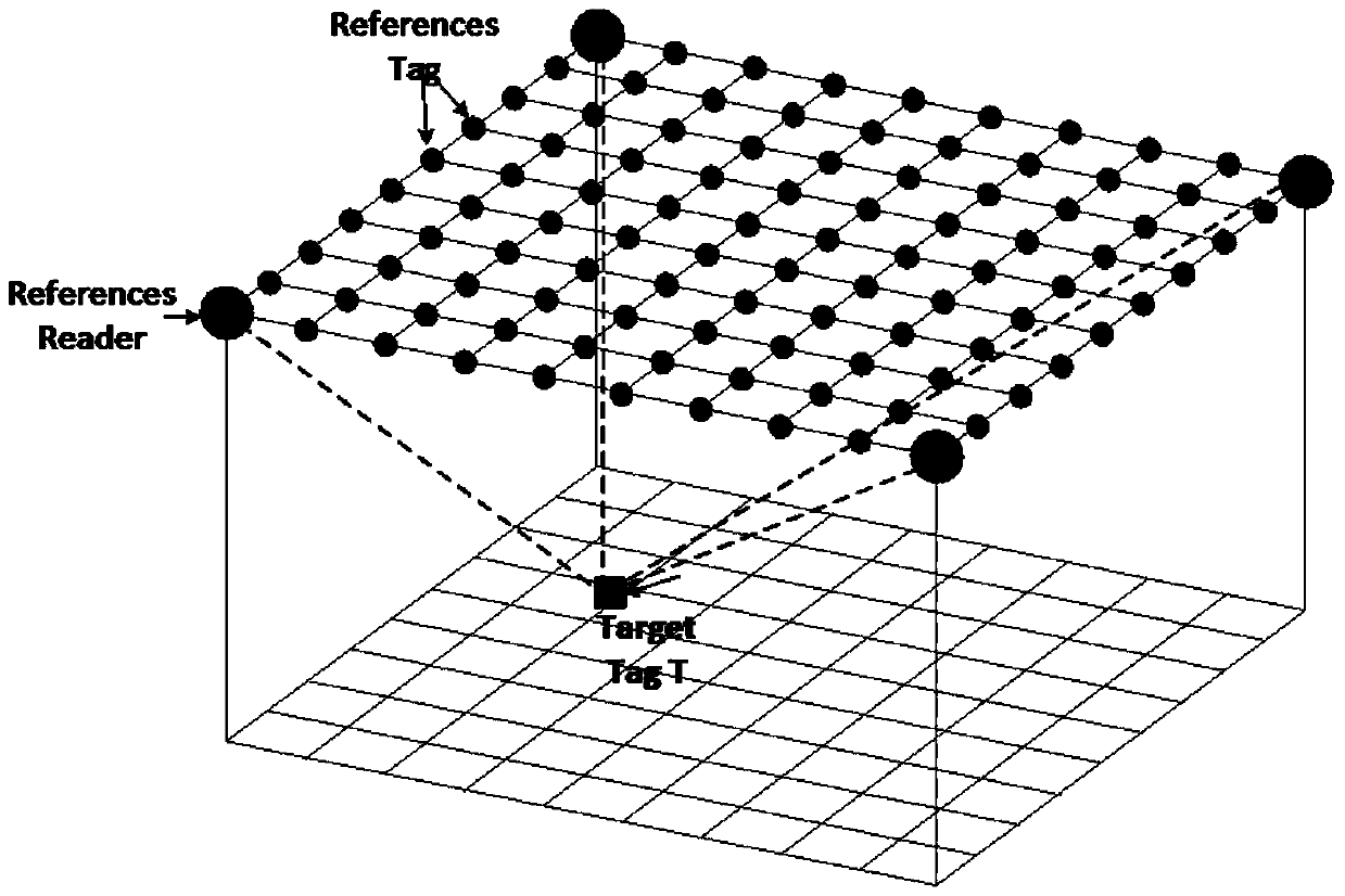
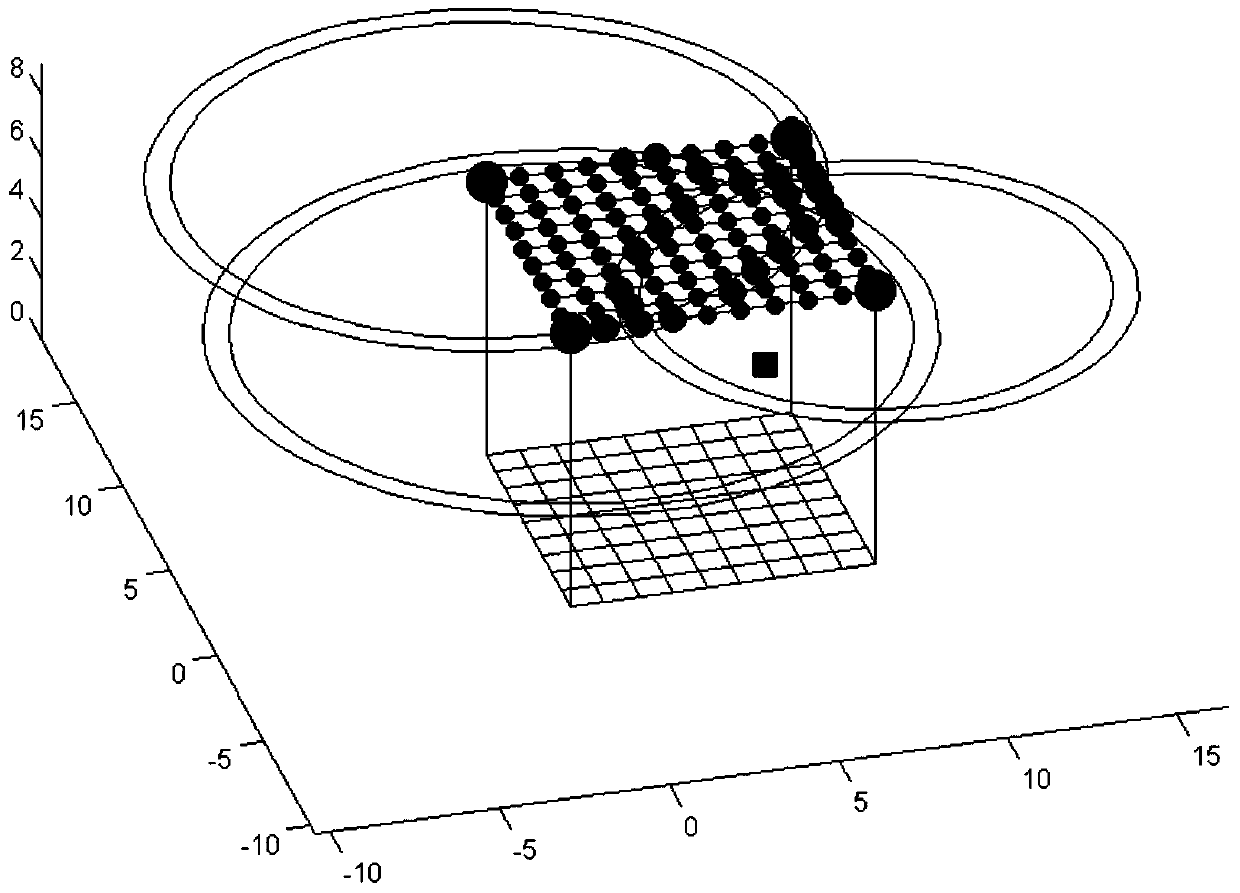
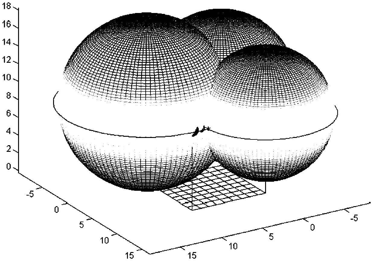
[0026] Such as figure 1 , figure 2 , image 3 , Figure 4 As shown, this algorithm includes three parts, 1. Signal strength classification; 2. Three-sphere intersection calculation; 3. Least square method plane fitting

[0027] The basic components of this system include RFID readers, RFID passive reference tags, and target tags to be located. The system deployment of this algorithm is as follows: figure 1 As shown, in the preprocessing stage, the passive reference tags with known coordinate positions are deployed on the upper plane of the hexahedron. By default, four readers are deployed on the fou...


PUM


Abstract

The invention discloses a three-dimensional space positioning method based on RFID (Radio Frequency Identification) middleware. The method comprises the steps of dividing the signal intensity level of a reader, dividing maximum signal intensity level and minimum signal intensity level according to the signal intensity of a read target label, estimating the distance between the reader and the target label according to a reference label set between the maximum and minimum signal intensity levels, calculating a three-ball intersection formula to obtain an estimated coordinate point of the target label, and finally performing least square plane fitting to obtain an estimated coordinate of the target label. The architecture design integrating the algorithm and the RFID middleware adopts a data fusion module, a positioning algorithm factory module and a Web view module, wherein by integrating the algorithm and the RFID middleware, the existing RFID middleware can be expanded, and the development cycle of RFID positioning layout can be shortened.

Description

technical field [0001] The patent of the present invention relates to the technical field of RFID, a three-dimensional space positioning algorithm, and positioning middleware, and in particular to a method for realizing three-dimensional space positioning based on RFID middleware. Background technique [0002] Object localization is very important in the application of tracking of moving objects and sensing the presence of objects. Existing solutions include Global Positioning System (GPS), Wi-Fi, Bluetooth, ZigBee, RFID and RFID UWB technologies as possible solutions have been extensively researched. From the comparison and measurement of four aspects of cost, accuracy, range, and energy consumption, we can analyze that RFID UWB has better advantages. RFID UWB is derived from early RFID technology, but has higher bandwidth and higher positioning. Accuracy, RFID UWB has become the preferred solution for positioning. [0003] The basic RFID system consists of tags, antennas...

Claims


Application Information

Patent Timeline
Patent Type & Authority Patents(China)
IPC IPC(8): G01S5/08
CPCG01S5/08
Inventor 刘发贵罗松超钟德祥
Owner SOUTH CHINA UNIV OF TECH
Learn More