LED lamp bar drive circuit and dimming method thereof, backlight module and display device

A technology for LED strips and driving circuits, which can be used in the layout of electric lamp circuits, electric light sources, lighting devices, etc., and can solve problems such as flickering or noise.

Inactive Publication Date: 2015-11-25
BOE TECH GRP CO LTD +1
View PDF5 Cites 15 Cited by
  • Summary
  • Abstract
  • Description
  • Claims
  • Application Information

AI Technical Summary

Problems solved by technology

[0004] The present invention aims at the problem that the existing PWM dimming easily causes flicker or noise, and provides an LED light strip driving circuit, its dimming method, a backlight module and a display device

Method used


Image

  • LED lamp bar drive circuit and dimming method thereof, backlight module and display device
  • LED lamp bar drive circuit and dimming method thereof, backlight module and display device
  • LED lamp bar drive circuit and dimming method thereof, backlight module and display device

Examples


Embodiment 1

[0032] This embodiment provides an LED light bar driving circuit for driving an LED light bar. The LED light bar includes a plurality of branches, and each branch is provided with one LED lamp or a plurality of LED lights in series, and one end of each branch Both are connected to the first input terminal, and the other terminals are respectively a plurality of independent second input terminals;

[0033] The LED strip driving circuit includes:

[0034] A power supply unit, which includes a first output terminal for connecting to the first input terminal, and a plurality of second output terminals respectively for connecting to each second input terminal, wherein each second output terminal is connected in parallel, and it is used for Periodic output voltage;

[0035] The current detection unit is used to detect the average value of the total current input into the LED light bar;

[0036] The control unit is used to control the opening and closing of each second output end a...

Embodiment 2

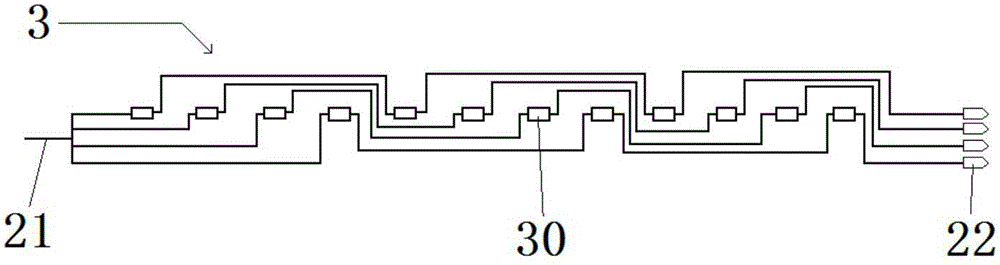
[0039] Such as Figure 1-2 As shown, this embodiment provides an LED light bar drive circuit for driving the LED light bar 3, the LED light bar 3 includes a plurality of branches, and each branch is provided with an LED lamp 30 or a plurality of LED lights in series Lamp 30, one end of each branch is connected to the first input end 21, and the other end is respectively a plurality of independent second input ends 22;

[0040] The LED strip driving circuit includes:

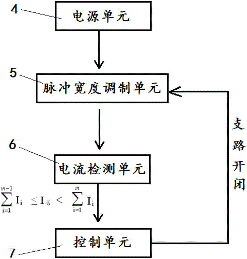
[0041] A power supply unit 4, which includes a first output terminal for connecting to the first input terminal 21, and a plurality of second output terminals respectively for connecting to each second input terminal 22, wherein each second output terminal is connected in parallel, and It is used to provide voltage periodically;

[0042] The current detection unit is used to detect the average value of the total current input into the LED light bar 3;

[0043] The control unit is configured to control the open...

Embodiment 3

[0051] This embodiment provides a dimming method for the LED light bar driving circuit in Embodiment 2, which includes the following steps:

[0052] S1, the periodic output voltage of the power supply unit 4;

[0053] S2. The current detection unit 6 detects the average value of the total current input into the LED light bar 3;

[0054] S3. The control unit 7 controls the opening and closing of each second output end according to the detection result of the current detection unit 6, and the power supply unit 4 changes the magnitude of the output voltage according to the opening and closing of each second output end.

[0055] That is to say, when it is detected that the average value of the total current input in the LED light bar 3 decreases, the corresponding branch is closed, and the situation of closing the branch is fed back to the power supply unit 4, and the power supply unit 4 Switching changes the output voltage to keep the current in each branch within a predetermine...


PUM


Abstract

The invention provides an LED lamp bar drive circuit and a dimming method thereof, a backlight module and a display device, belongs to the technical field of display, and can solve the problem that existing PWM dimming can cause flickering or noise easily. The LED lamp bar drive circuit comprises a power supply unit for providing voltage for each branch of LED lamps, a current detection unit for detecting average value of total current input to LED lamp bars, and a control unit for controlling the LED lamps on each branch to be turned on/off according to the detection result of the current detection unit. The brightness of the LED lamp bars can be adjusted by controlling the on/off state of the lamps on the corresponding branch. The dimming method is high in efficiency, low in noise, and wider in dimming range. The LED lamp bar drive circuit is suitable for adjusting the brightness of various types of backlight modules.

Description

technical field [0001] The invention belongs to the field of display technology, and in particular relates to an LED light bar drive circuit, a dimming method thereof, a backlight module and a display device. Background technique [0002] Currently, LCD TVs and monitors that use LED lamps as the light source in the backlight generally use PWM (PulseWidthModulation, pulse width modulation) to adjust the brightness of the backlight. The adjustment principle is to keep the maximum output current of the LED lamp drive module unchanged, and to control the average current by increasing or decreasing the conduction time through PWM control, and then control the brightness of the LED lamp, that is, PWM controls the duty cycle (backlight The current on-off time ratio) changes the effective value of the backlight current to achieve the purpose of changing the brightness of the LED lamp. [0003] The inventors have found that at least the following problems exist in the prior art: due...

Claims


Application Information

Patent Timeline
Patent Type & Authority Applications(China)
IPC IPC(8): G09G3/34H05B37/02
Inventor 李建军张子鹤陈涛
Owner BOE TECH GRP CO LTD
Why Eureka
Try Eureka