

Load voltage compensation circuit for light-emitting diode (LED) driving
A technology of LED drive and load voltage, applied in the field of compensation circuit, can solve the problems of increasing circuit cost and achieve the effects of high output current accuracy, simplified application circuit, and simplified peripheral circuit
- Summary
- Abstract
- Description
- Claims
- Application Information
AI Technical Summary
Problems solved by technology
Method used
Image

Examples
Embodiment Construction
[0019] The working principle of the present invention will be further described in detail below in conjunction with the accompanying drawings and preferred solutions.
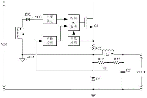
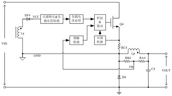
[0020] as attached Figure 4 Shown is a circuit block diagram of the present invention, specifically a block diagram of a load voltage compensation circuit for LED driving, the circuit includes a transformer, a current detection module, a degaussing detection module, a control drive module, a switch tube (Q6), Sampling resistor (RC6), voltage dividing resistor (RA6, RB6), load voltage detection module, sample hold module and load voltage compensation module. The transformer only includes the main winding (Lp), the load voltage detection module, the sample hold module and the load voltage compensation module are connected in series; the output terminal of the load voltage compensation module is connected to the control drive module; It also leads to a feedback detection terminal (FB), which is connected to the ...
PUM
 Abstract
Description
Claims
Application Information