Dimming circuit and dimming control method

a dimming control and circuit technology, applied in the direction of electric variable regulation, process and machine control, instruments, etc., can solve the problems of increasing power loss, reducing load accuracy, and reducing load current accuracy, so as to increase the output current accuracy

Active Publication Date: 2020-05-14
DELTA ELECTRONICS SHANGHAI CO LTD
View PDF4 Cites 0 Cited by
  • Summary
  • Abstract
  • Description
  • Claims
  • Application Information

AI Technical Summary

Benefits of technology

[0006]An object of the present invention provides a dimming circuit and a dimming control method for increasing the accuracy of an output current.

Problems solved by technology

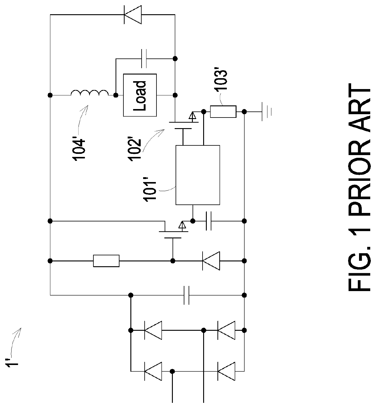
However, since the control circuit 101′ doesn't directly control the operation of the power switch 102′ according to the current of the load, which result in decrease of the accuracy of the load current.
Moreover, while the current flowing through the sampling resistor 103′, which results in the increase of the power loss.
In other words, there will be an error between the output current of the dimming circuit 1′ and the preset ideal output current, which will result in the decrease of the accuracy of the load.

Method used


Image

  • Dimming circuit and dimming control method
  • Dimming circuit and dimming control method
  • Dimming circuit and dimming control method

Examples


first embodiment

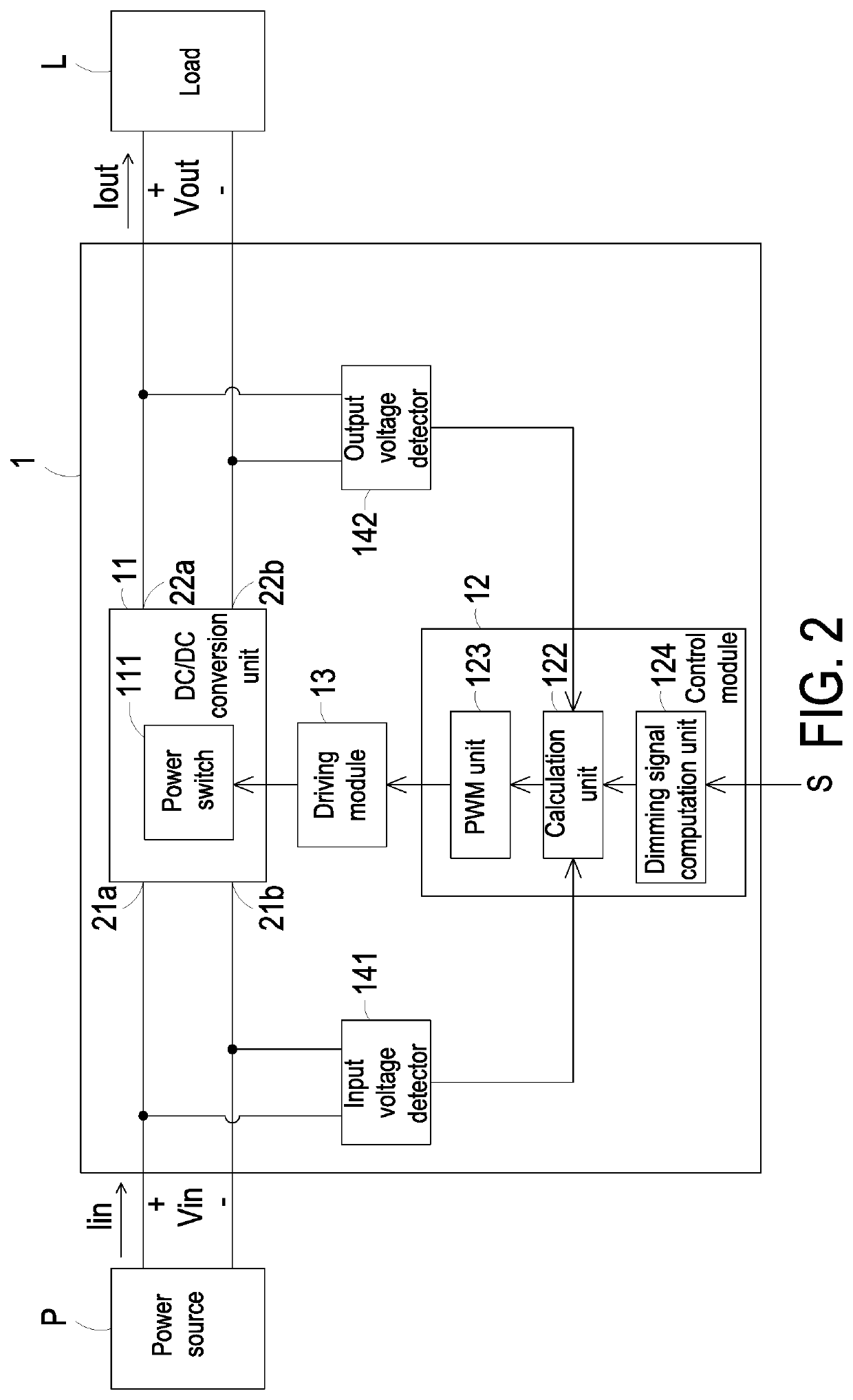
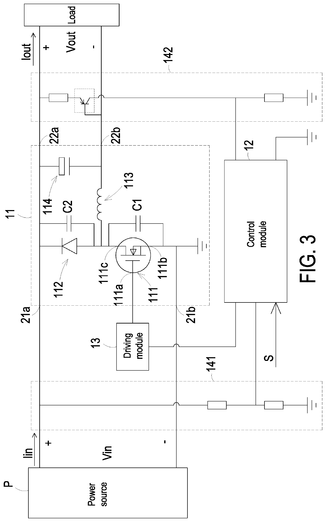
[0050]Referring to FIG. 8A and FIGS. 2 to 6. FIG. 8A is a schematic timing waveform diagram illustrating plural switching periods of the switch control signal according to the present invention. In this embodiment, each switching period of the switch control signal is controlled according to the PWM signal related with the variation period signal. The calculation unit 122 sets the period of the variation period signal equal to an oscillation period Tc. The variation period signal has a trend waveform of a cyclic triangular wave or a cyclic sine wave. In this embodiment, each switching period of the switch control signal is controlled according to the PWM signal containing the variation period signal, and the each switching period is gradually changed by a setting variation ΔT. In some embodiments, the setting variation ΔT is equal to Tc / n, wherein Tc is the oscillation period, and n is an integer not lower than 2. In this embodiment, the variation period signal has the waveform of a...

second embodiment

[0055]FIG. 8B is a schematic timing waveform diagram illustrating plural switching periods of the switch control signal according to the present invention. The time duration of the switching period reference is equal to Ts. Then, the time duration of each switching period is gradually decreased by the setting variation ΔT. The time duration of the first switching period after the switching period reference is equal to Ts−ΔT (=Ts−Tc / n). The time duration of the second switching period after the switching period reference is equal to Ts−2ΔT (=Ts−2Tc / n). The rest may be deduced by analogy until the time duration of the switching period (also referred as the smallest switching period) reaches Ts−Tc / 2. Then, the time duration of each switching period is gradually increased by the setting variation ΔT. The time duration of the first switching period after the smallest switching period is equal to Ts−Tc / 2+Tc / n. The time duration of the second switching period after the smallest switching p...


PUM


Abstract

A dimming circuit includes a DC/DC conversion unit and a control module. The control module provides a switching period reference, and samples an input voltage and an output voltage. The control module calculates a turn-on time according to the input voltage, the output voltage and a reference current signal. The control module generates a variation period signal which is cyclically-changed. The variation period signal is combined with the switching period reference or the turn-on time. Consequently, a pulse width modulation signal cyclically changed is generated by the switching period reference, the turn-on time and the variation period signal. Since the switching periods is cyclically changed, the average of the output current is close to the ideal value.

Description

FIELD OF THE INVENTION[0001]The present invention relates to a dimming circuit and a dimming control method, and more particularly to a dimming circuit and a dimming control method for increasing the accuracy of an output current.BACKGROUND OF THE INVENTION[0002]Lighting technology, such as LEDs, is developing towards energy saving and environmental protection. Generally, the brightness of the LEDs is proportional to the driving current. So a dimming circuit for driving the LEDs needs to provide a stable driving current to ensure the safety of LEDs and achieve brightness and accuracy required by the consumer. Therefore, it is important for the dimming circuit to output the stable driving current to the LEDs.[0003]FIG. 1 is a schematic circuit diagram illustrating a conventional dimming circuit. The dimming circuit 1′ is used for driving a load such as a LED device. The dimming circuit 1′ comprises a control circuit 101′. The control circuit 101′ detects the current flowing through a...

Claims


Application Information

Patent Timeline
Patent Type & Authority Applications(United States)
IPC IPC(8): H05B33/08H02M3/156H05B44/00
CPCH05B45/10H02M3/156H05B45/37H02M7/2176H05B45/325
Inventor FU, XIAOPINGZHANG, XINGHUA
Owner DELTA ELECTRONICS SHANGHAI CO LTD
Why Eureka
Try Eureka