Device and method for the non destructive testing of tyres by tomography

A technology of tomography and tires, applied in the field of non-destructive inspection, representation of tomography images, and devices implementing the method, which can solve problems such as slow tire inspection, parameterization and setup of extended equipment, and complexity

Active Publication Date: 2015-11-25
CYXPLUS
View PDF8 Cites 3 Cited by
  • Summary
  • Abstract
  • Description
  • Claims
  • Application Information

AI Technical Summary

Problems solved by technology

However, this device presents a number of disadvantages
First, the inspection of tires is slow because it requires multiple cycles of relative displacement between the source-detector arrangement on the one hand and the tire on the other hand, which in turn includes round trips along the transverse linear axis and angles according to rotational motion. increase
Furthermore, when the device is used to inspect tires of substantially different sizes, these relative displacement periods must be modified, which complicates and extends the parameterization and setup of the device based on tire size variations

Method used


Image

  • Device and method for the non destructive testing of tyres by tomography
  • Device and method for the non destructive testing of tyres by tomography
  • Device and method for the non destructive testing of tyres by tomography

Examples


Embodiment Construction

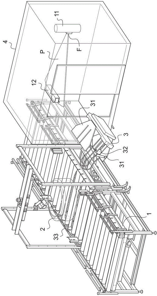
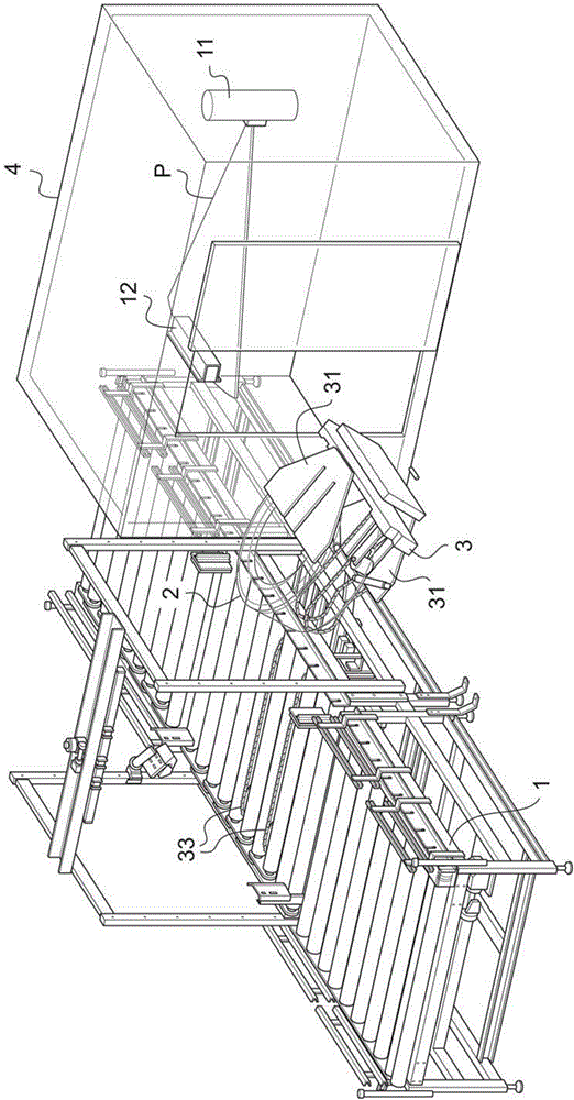
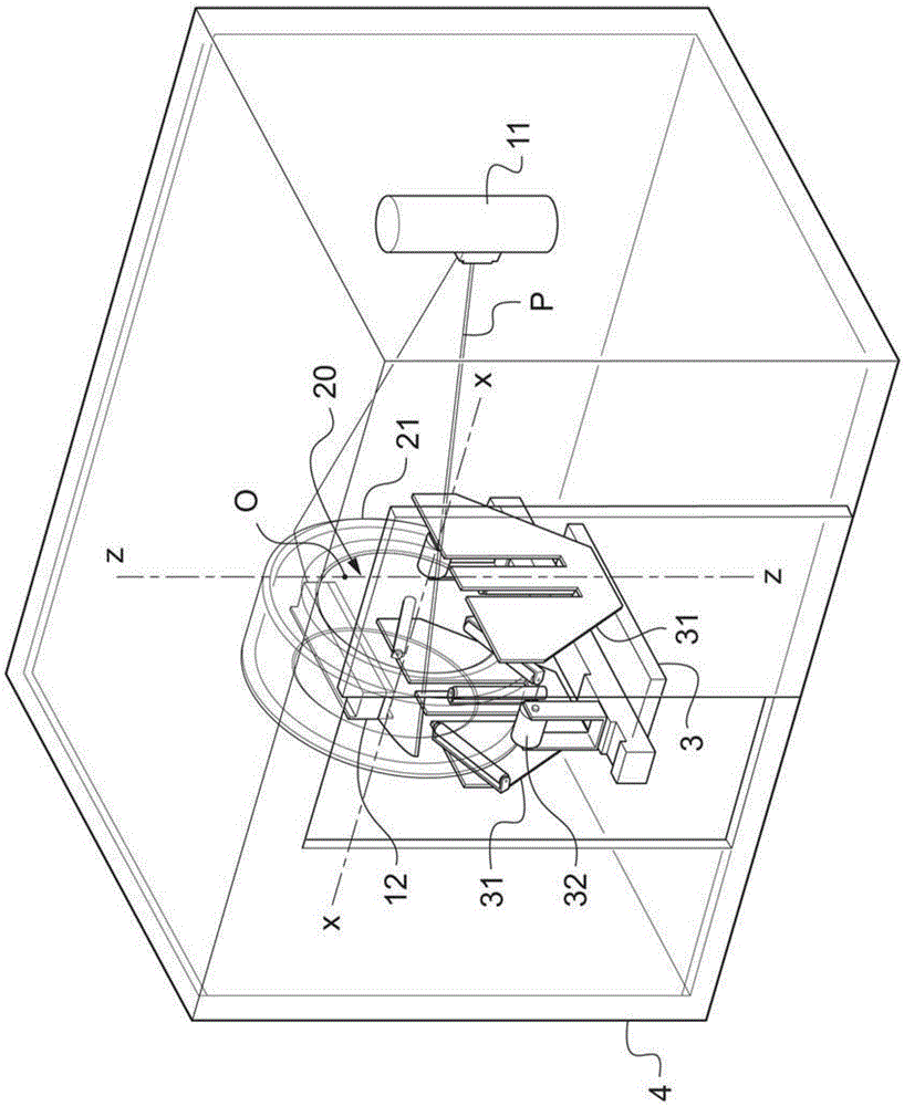
[0039] The device for inspecting tires by tomography according to the invention is incorporated into a tire production line. The infeed conveyor 1 for the tire 2 cooperates with the steering stand 3 to transfer the tire 2 from the infeed conveyor 1 to the examination chamber 4, which has an X-ray impermeable wall, in which the X-ray source 11 and the X-ray detector 12. This detector 12 may be a linear or matrix detector and is arranged horizontally in the examination chamber 4 facing the source 11 . The source 11 is preferably equipped with a collimator such that the radiation is emitted in the form of a planar beam of horizontal axis, which defines a cross-sectional plane P, also called the emission plane, which passes through the focal point F of the source 11 and the horizontally positioned detector 12 .

[0040] The steering stand 3 of the tyres, comprising a frame supporting the motor drive system, is available for the stand 3 so that it can be placed on rails (not show...


PUM

PropertyMeasurementUnit
thicknessaaaaaaaaaa
widthaaaaaaaaaa
widthaaaaaaaaaa

Abstract

The invention relates to a device for testing a tyre (2) for representing tomographical images of sections of casing of said tyre, comprising a source (11) of ionizing radiation arranged outside said tyre (2) and a detector (12) for receiving said radiation, said detector (12) being situated opposite said source (11) with respect to at least one section of casing, the axis (X-X) of said tyre running parallel to a sectional plane (P) passing through the focus (F) of said source (11) and said detector (12), whereas said tyre and the source-detector assembly are moved with a rotational motion relative to one another about an axis of rotation (Z-Z) perpendicular to said sectional plane (P), according to a predetermined angular excursion range. According to the invention, said detector (12) is designed to be disposed in a central internal zone (20) of said tyre (2) during the implementation of a testing cycle.

Description

technical field [0001] The invention relates to a tomographic inspection method based on X-ray detection of tires for non-destructive inspection of its internal mechanism. The invention also relates to a device for carrying out the method. More specifically, the method and device according to the invention are used for the representation of tomographic images of tire slices. Background technique [0002] Acquiring a tomographic image of a portion of an object using a tomographic apparatus comprising a source-detector assembly includes directing an incident beam of X-rays towards the object, while a detector is capable of measuring the absorption of X-rays passing through the object, which is linked to the Study the material density of an object. A variety of scans are known and the controlled direction may be known. After appropriate digital processing of the signals collected on the detection unit of the detector, the absorption value of X-rays at each point in the cross-...

Claims


Application Information

Patent Timeline
Patent Type & Authority Applications(China)
IPC IPC(8): G01N23/18G01M17/03
CPCG01N23/185G01M17/028G01N2223/627G01N23/083G21K1/02
Inventor A.德克鲁F.菲卡洛拉O.鲁鲍德O.弗朗索瓦
Owner CYXPLUS
Why Eureka
Try Eureka