Power conditioning and saving device

A technology of energy storage device and compression device, which is applied to circuit devices, electrical components, AC network circuits, etc., and can solve problems such as damage to equipment, useful use by users, and inability of spikes and harmonics.

Inactive Publication Date: 2015-11-25
POWERMAG
View PDF7 Cites 2 Cited by
  • Summary
  • Abstract
  • Description
  • Claims
  • Application Information

AI Technical Summary

Problems solved by technology

Although spikes and harmonics pass through the power meter, these spikes

Method used


Image

  • Power conditioning and saving device
  • Power conditioning and saving device
  • Power conditioning and saving device

Examples


Embodiment Construction

[0058] Various embodiments and aspects of the invention will be described with reference to details discussed below, and the accompanying drawings will illustrate the various embodiments. The following description and drawings illustrate the invention and should not be construed as limiting the invention. Various specific details are described in order to provide a thorough understanding of various embodiments of the invention. However, in some instances, well-known or conventional details are not described in order to provide a concise discussion of embodiments of the invention.

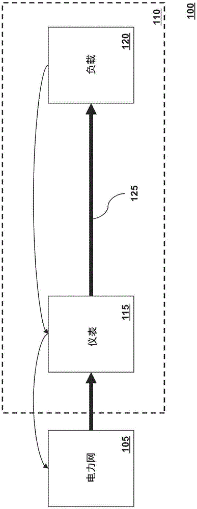
[0059] figure 1 An exemplary power system 100 is shown. The power company provides power to the power grid 105 . Electricity is delivered to consumers 110 via the power grid 105 as electrical energy. The user 110 has a meter 115 provided by the power company to measure the power consumed by the user 110 . Power is consumed by one or more loads 120 operated by user 110 . Ideally, all of the ele...


PUM


Abstract

Systems and methods are disclosed herein to a power factor adjuster comprising: a power factor measurement unit configured to measure the power factor on an input line to a load and generate a power factor correction signal based on the measured power factor; and a power factor adjustment unit connected to the power factor measurement unit comprising: a fixed capacitor connected in series to a first switching device; and an adjustable element having a variable capacitance connected in parallel to the fixed capacitor and in series to a second switching device, wherein the overall capacitance of the power factor adjustment unit is adjusted by adjusting the capacitance of the adjustable element or by toggling the first and second switching devices in response to the power factor correction signal.

Description

technical field [0001] The present invention relates generally to the supply of electrical power. More specifically, the present invention relates to reducing power consumption in power delivery systems. Background technique [0002] Power companies and power company customers share a common interest in reducing the amount of electricity wasted in power distribution systems. Power companies engineer transmission lines, transformers and generators to provide the electricity that customers will pull away. Even though customers don't use some of the power they pull away, utilities still make engineers transmission lines, transformers and generators provide this extra wasted power. In addition, some of the electricity transmitted to the user is not used or wasted by the user, but is "reflected" back to the power generator. Thus, the transmission line has to carry both the power being transmitted and the power being reflected back. Not only does this mean that transmission li...

Claims


Application Information

Patent Timeline
IPC IPC(8): H01G5/16
CPCH02J3/1828Y02E40/30
Inventor 罗伯特·V·艾伯森
Owner POWERMAG
Why Eureka
Try Eureka