A kind of concrete retaining wall scupper hole greening structure and method

A technology of retaining wall and scupper hole, applied in the field of construction engineering, can solve the problems of backfill soil loss, poor appearance and scouring in front of the wall, and achieve the effects of reducing the peak value of rain and flood, convenient construction and simple design

Active Publication Date: 2017-08-08
CMCU ENG
View PDF6 Cites 0 Cited by
  • Summary
  • Abstract
  • Description
  • Claims
  • Application Information

AI Technical Summary

Problems solved by technology

After the weep hole on the concrete wall has water out, it is prone to efflorescence along the wall surface, which affects the durability of the structure and has a very poor appearance; the scattered flow of the concrete weep hole is easy to cause scour to the backfill soil in front of the retaining wall, which will cause the wall to be damaged over time. Part of the former backfill soil is lost, and the bearing capacity of the foundation at the toe of the wall is softened and the bearing capacity is reduced

Method used


Image

  • A kind of concrete retaining wall scupper hole greening structure and method
  • A kind of concrete retaining wall scupper hole greening structure and method

Examples


Embodiment Construction

[0027] The preferred embodiments of the present invention will be described in detail below with reference to the accompanying drawings.

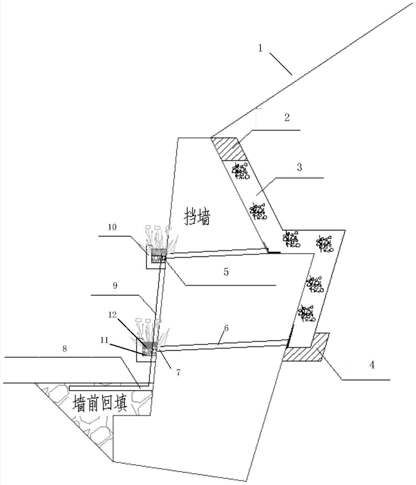
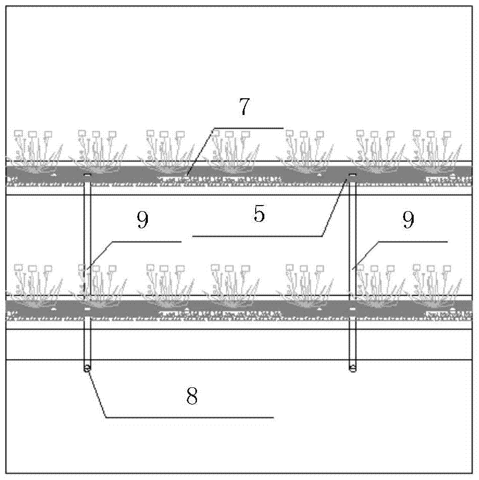
[0028] A kind of concrete retaining wall weep hole greening structure provided by the present invention, its sectional view is as follows figure 1 As shown, the front of the structure is shown as figure 2 As shown, there is a groove under the weep hole of the retaining wall. The groove includes a water-permeable layer and a planting soil layer. The planting soil layer is laid on the water-permeable layer. The planting soil layer is used for planting plants. A layer of permeable geotextile is provided between the layers. Spring permeable pipes are laid in the permeable layer. The spring permeable pipes are arranged horizontally along the groove. The spring permeable pipes control the water level in the groove through the height of the interface with the downpipe. The retaining wall is vertically provided with downspouts at certain distance...


PUM


Abstract

The invention relates to a concrete retaining wall drainage hole greening structure and method and belongs to the technical field of construction engineering. Retaining wall drainage holes are provided with grooves capable of draining water and storing water respectively, the grooves internally comprise permeable layers and planting soil layers, the planting soil layers are arranged on the permeable layers, and the planting soil layers are used for planting plants. Permeable geotextile is laid between the planting soil layers and the permeable layers. The permeable layers are internally provided with spring permeable pipes. A retaining wall is provided with water falling pipes. The spring permeable pipes are connected into the water falling pipes, and water falling pipes are connected into an urban sewage system or a detention and retention facility. The concrete retaining wall drainage hole greening structure and method are simple in design, convenient to construct and capable of enhancing the durability and reliability of the concrete retaining wall; meanwhile, the surface of concrete is greened and beautified; the structure can store water as well, and the construction concept of wisdom city and sponge city is achieved.

Description

technical field [0001] The invention belongs to the technical field of construction engineering, and relates to a greening structure and method for a drain hole of a concrete retaining wall. Background technique [0002] With the development of society and the rapid advancement of urbanization, there are many protective structures in urban construction. Many retaining structures are concrete members with a cold and hard appearance. After water comes out of the weep hole on the concrete wall, it is easy to efflorescence along the wall surface, which affects the durability of the structure and has a very poor appearance; the scattered flow of the concrete weep hole is easy to cause erosion of the backfill soil in front of the retaining wall, which will cause wall damage over time. Part of the former backfill soil is lost, and the bearing capacity of the ground at the toe of the wall is softened and the bearing capacity is reduced. [0003] The setting of plants can beautify ...

Claims


Application Information

Patent Timeline
Patent Type & Authority Patents(China)
IPC IPC(8): A01G9/02E02D29/02
CPCA01G9/02E02D29/02
Inventor 邓道祥谭洪强
Owner CMCU ENG
Why Eureka
Try Eureka