a lunch break chair
A technology for lunch break chairs and chair seats, which is applied in the field of lunch break chairs, can solve the problems of inconvenient adjustment methods, few angles for positioning the back of the chair, and positioning at two angles, vertical and inclined, to achieve simple structure, overall solidity, and high positioning angle. many effects
- Summary
- Abstract
- Description
- Claims
- Application Information
AI Technical Summary
Problems solved by technology
Method used
Image
Examples
Embodiment 1
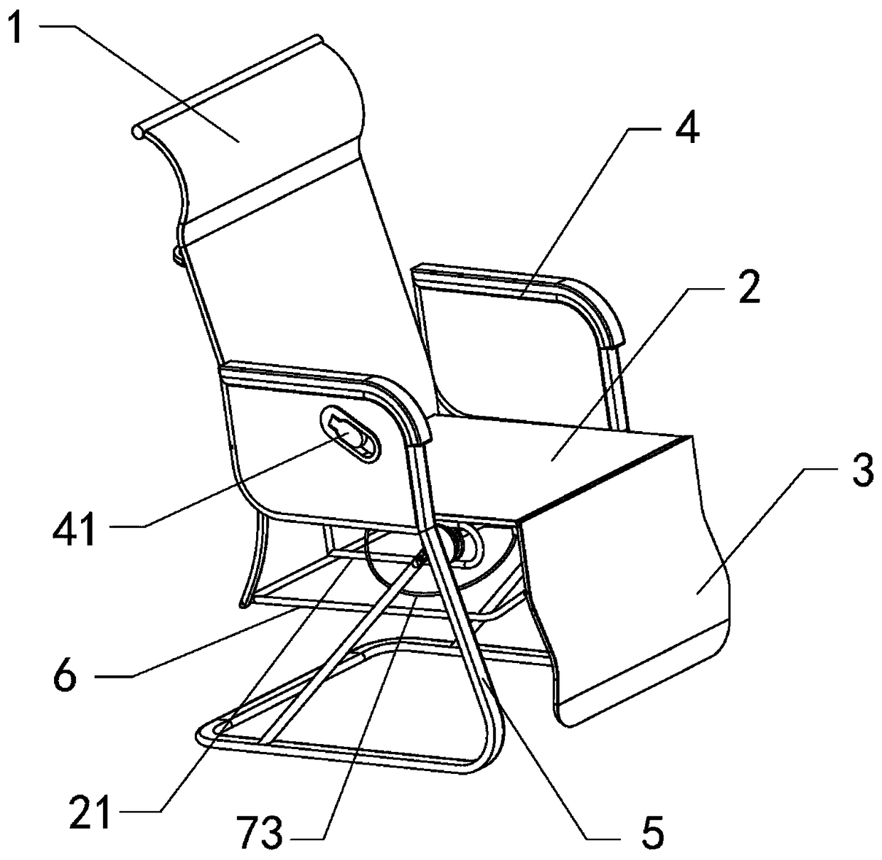
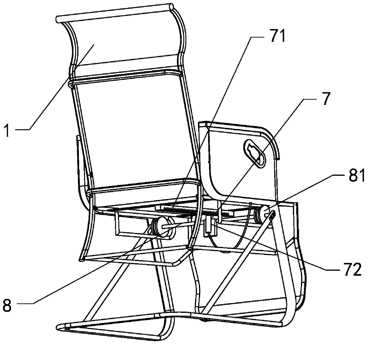
[0029] according to figure 1 , figure 2 Shown, a kind of lunch break chair comprises, backrest 1, seat 2, leg frame 3, armrest 4 and chair leg 5, wherein, backrest 1 and seat 2 are hinged, and the angle between the two can be adjusted; 2 is hinged with the leg frame 3, and the angle between the two can be adjusted; a swing rod 6 is arranged between the backrest 1 and the leg frame 3, and the two ends of the swing rod 6 are respectively hinged with the backrest 1 and the leg frame 3; A guide rail frame 21 is provided, and a positioning mechanism 7 is arranged between the guide rail frames 21 below the seat base 2; The backrest 1, the seat 2, the leg frame 3 and the swing rod 6 form a double rocker mechanism, so that the backrest 1 and the leg frame 3 can swing in linkage. Lock in position.
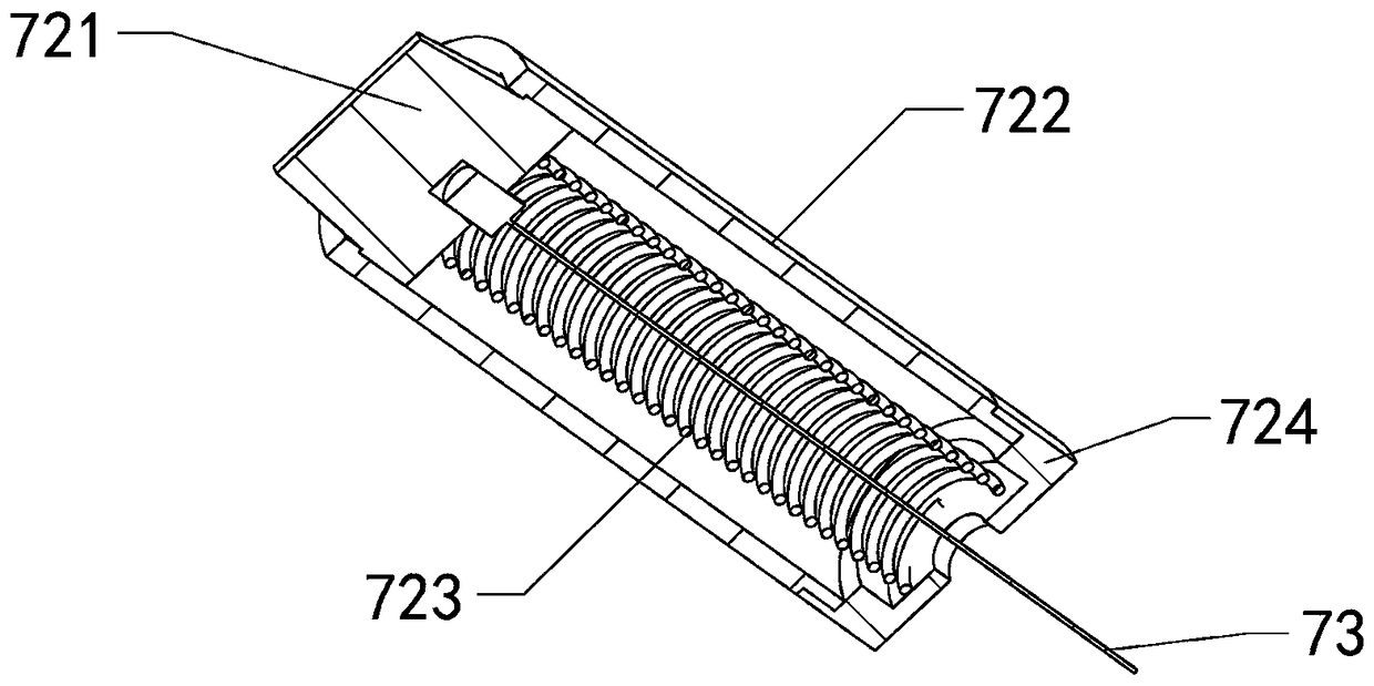
[0030] according to figure 2 As shown, the position adjustment mechanism 7 includes: a rack 71 arranged below the seat 2, a spring pin 72 arranged on the guide rod 8 and a control wir...
Embodiment 2
[0039] The difference from the above-mentioned embodiment 1 is that, according to Image 6 As shown, the chair leg 5 is divided into a left chair leg and a right chair leg, which are arranged on both sides of the seat 2 respectively, and a connecting rod 51 is arranged between the two chair legs. This structure can greatly reduce the packing capacity after the chair is disassembled The volume makes it easy to pack and transport the chair.
Embodiment 3
[0041] The difference from the above-mentioned embodiment 1 is that, according to Figure 7 As shown, the joint between the chair leg 5 and the guide rod 8 is provided with an anti-rotation mechanism 9 for preventing the rotation of the guide rod 8. The anti-rotation mechanism 9 includes two connection points, at least one of which does not pass through the axis of the guide rod 8, Therefore, it is ensured that the guide rod 8 will not rotate when it moves, and the stability of the position of the spring pin 7 fixed on the guide rod 8 is ensured.
PUM
 Abstract
Description
Claims
Application Information
 - R&D
- Intellectual Property
- Life Sciences
- Materials
- Tech Scout
- Unparalleled Data Quality
- Higher Quality Content
- 60% Fewer Hallucinations
Browse by: Latest US Patents, China's latest patents, Technical Efficacy Thesaurus, Application Domain, Technology Topic, Popular Technical Reports.
© 2025 PatSnap. All rights reserved.Legal|Privacy policy|Modern Slavery Act Transparency Statement|Sitemap|About US| Contact US: help@patsnap.com


