A modular box and assembly method for scr denitrification catalyst

The technology of a denitration catalyst and an assembly method, which is applied in the field of thermal power generation denitration system, can solve the problems of small flue gas flow area, uneven force on the catalyst unit, large material loss, etc., to prevent corrosion, prevent dislocation and drop, increase buffering effect

Inactive Publication Date: 2018-01-19
易能环境技术有限公司
View PDF4 Cites 0 Cited by
  • Summary
  • Abstract
  • Description
  • Claims
  • Application Information

AI Technical Summary

Problems solved by technology

[0004] In order to improve the existing technology, the present invention provides a modular box and an assembly method of an SCR denitrification catalyst, which are used to solve the shortcomings of the existing assembly process such as uneven stress on the catalyst unit, large material loss, and small flue gas flow area.

Method used


Image

  • A modular box and assembly method for scr denitrification catalyst
  • A modular box and assembly method for scr denitrification catalyst
  • A modular box and assembly method for scr denitrification catalyst

Examples


Embodiment 1

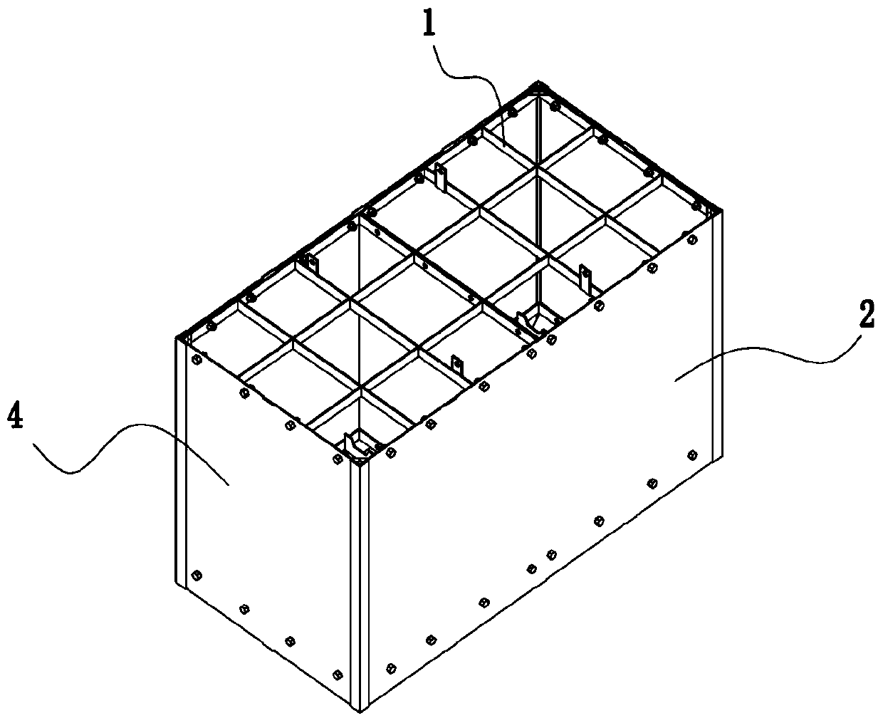
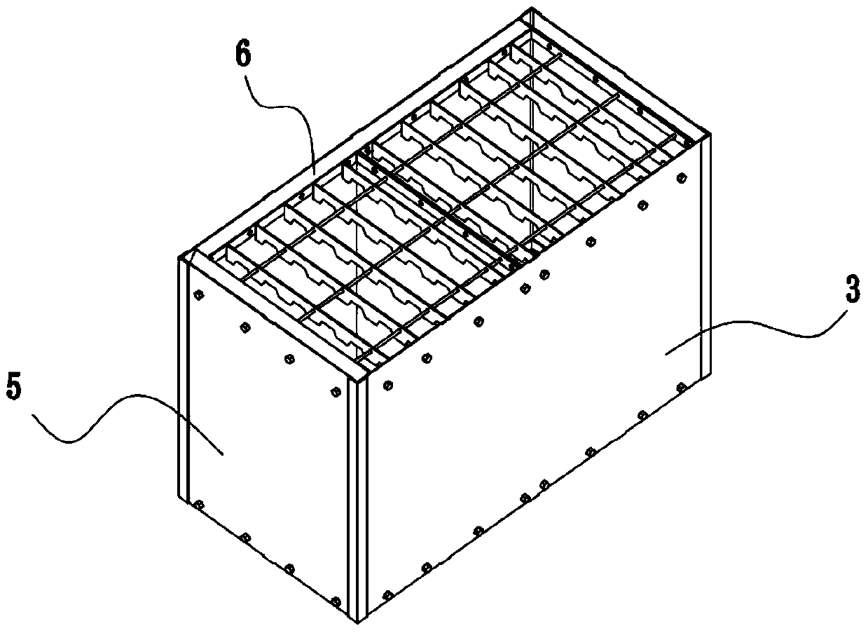
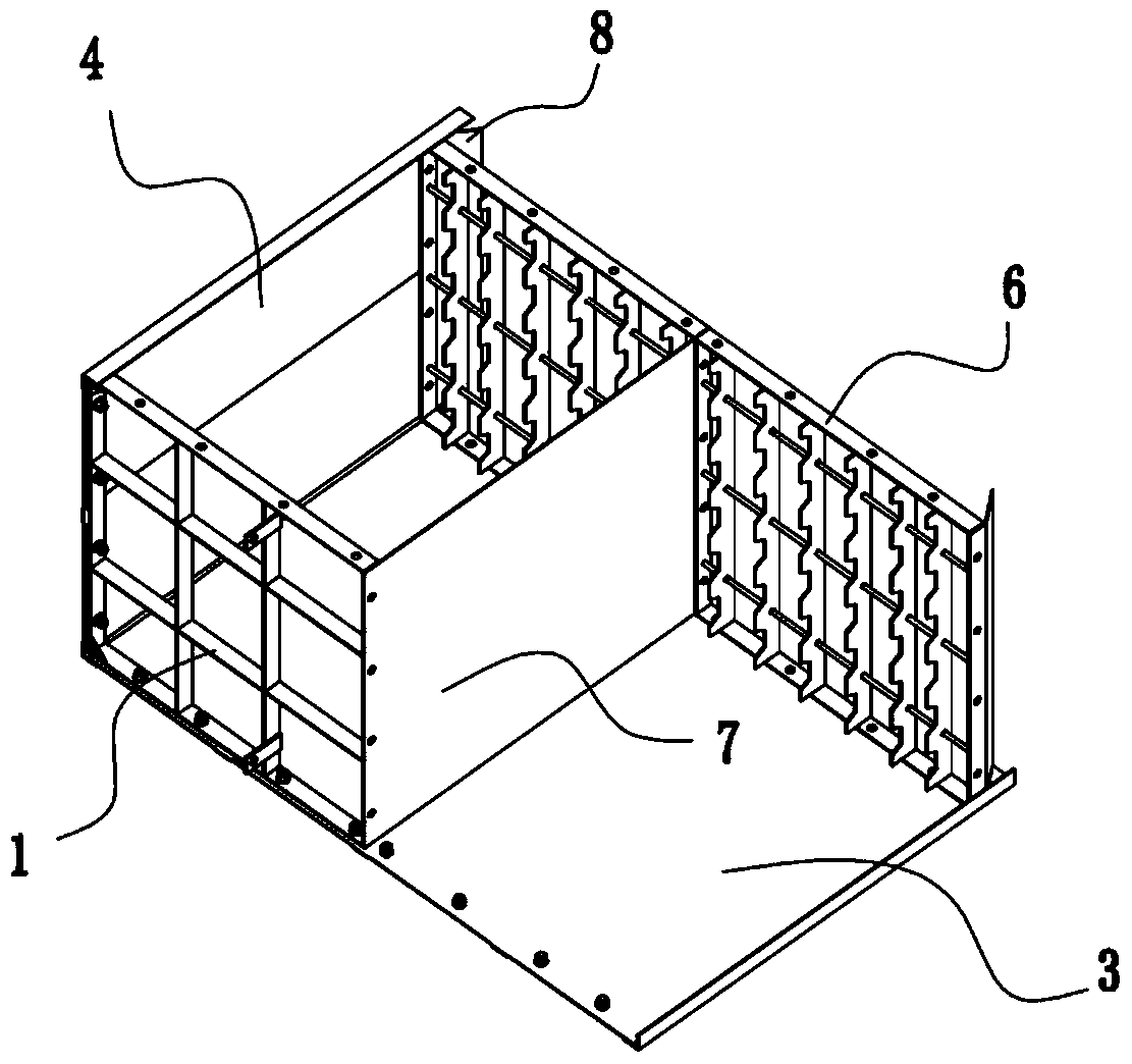
[0029] Referring to the accompanying drawings, a modular box for SCR denitrification catalyst, the box body of the modular box is mainly composed of a top plate 1, a front side plate 2, a rear side plate 3, a left side plate 4, a right side plate 5 and a bottom plate 6; The top plate 1 is a grid plate welded by steel plates, and the thickness direction of all steel plates in the top plate is kept perpendicular to the height direction of the box body. The bottom plate 6 is composed of a bottom frame 61 and a support plate 62, and the bottom frame is welded by steel plates. , the thickness direction of the same steel plate is perpendicular to the height direction of the box body; a plurality of support plates 62 are welded at intervals along the length direction on the bottom frame, and the support plates 62 are also steel plates, wherein one long side of the support plate 62 is tooth-shaped, The sides are vertically upward in the box body, and the tooth-shaped tooth grooves are ...

Embodiment 2

[0035] A method for assembling an SCR denitration catalyst module, comprising the module box in embodiment 1 and the cuboid catalyst unit installed in the module box, its specific assembly steps are as follows:

[0036] A) Place the rear side board horizontally on the assembly platform, install the left and right bottom boards first, and fix them on the rear side board through bolts passing through the left and right bottom boards and the bolt holes around the bottom board, and install the left and right bottom boards Install the middle partition at the same time, and clamp the two ends of the middle partition in the middle of the left and right bottom plates;

[0037] B) Fix the top plate on the rear side plate in the same way as step A);

[0038] C) Paste strip-shaped ceramic fiber gaskets on the left and right side walls of the intermediate partition; then arrange the cuboid catalyst units one by one in the box until the box is filled, wherein ceramic fiber gaskets are set ...


PUM


Abstract

A modular box and assembly method for SCR denitration catalyst, characterized in that, the box body of the modular box consists of a top plate, front, rear, left and right side plates, top plate and bottom plate; the top plate is a grid plate, The bottom plate is composed of a bottom frame and support plates arranged at intervals on the bottom frame. One side of the support plate is tooth-shaped, and the tooth-shaped side is set vertically upward; the top plate, front, rear, left 1. The right side plate, the top plate and the bottom plate are connected and fixed by bolt holes and bolts provided on the periphery of each plate, and there is a gap between the vertical sides of each side plate. The module box assembly method of the present invention can effectively control the pre-tightening force between the monomers in the module, and can ensure that each catalyst in the box and the inner wall of the box and each unit of the catalyst will move the catalyst through the friction generated between each other. The unit is fixed in the box, and the unit will not be damaged due to excessive pre-tightening force between the unit and the unit.

Description

technical field [0001] The invention relates to the technical field of a modular box of an SCR denitrification catalyst, which is used in a thermal power generation denitrification system. Background technique [0002] Nitrogen oxides (NO X Including NO, NO 2 and other compounds) is one of the main pollutants causing air pollution, the SCR system is NO X As the core of SCR denitration reaction, the quality and performance of the catalyst are directly related to the denitration efficiency. Therefore, the module box, as a protection device for the SCR catalyst, plays a vital role in maintaining the shape of the catalyst. [0003] The length of the denitrification catalyst is customized according to the project, that is, it is determined according to the amount of flue gas, the composition of the flue gas, etc., which requires the specification of the module box to change according to the length of the catalyst unit. The existing technology is to use the whole grid plate to ...

Claims


Application Information

Patent Timeline
Patent Type & Authority Patents(China)
IPC IPC(8): B01D53/88B01D53/56
Inventor 檀朝霞李蒴周宬裴浩陆龙飞徐晓明周珮萱
Owner 易能环境技术有限公司
Why Eureka
Try Eureka