
A precision crimping machine

A crimping machine, a precise technology, applied in metal processing, metal processing equipment, manufacturing tools, etc., can solve the problems of large space occupied by the crimping machine, difficult to guarantee the crimping accuracy, unreliable workpiece positioning, etc., and achieve high work efficiency. , The effect of high crimping accuracy and firm and reliable workpiece fixation

Active Publication Date: 2017-04-12
长沙礼恩派拉线工业有限公司
View PDF10 Cites 0 Cited by
  • Summary
  • Abstract
  • Description
  • Claims
  • Application Information

AI Technical Summary

Problems solved by technology

[0002] The traditional crimping machine takes up a lot of space and the working space is small, and because of the unreliable positioning of the workpiece, it often happens that the workpiece passes during the pressing process, causing the pressing position to deviate and affecting the product quality, and it is usually a single crimping joint. The production efficiency is low. When multiple stations need to be pressed, the position of the workpiece must be adjusted frequently. Repeated positioning of the workpiece will cause errors in the positioning of the workpiece, and a large deviation will inevitably be formed in the crimping position. Moreover, the die drives the press. When the joint moves down until it touches the workpiece, the crimping joint often deviates unpredictably relative to the workpiece, and the crimping accuracy is difficult to guarantee. For workpieces that require high crimping precision, the qualified rate of finished products is low

Method used


Image

  • A precision crimping machine

Examples


Embodiment Construction

[0014] The present invention will be further described below in conjunction with the accompanying drawings. The following examples are only used to illustrate the technical solution of the present invention more clearly, but not to limit the protection scope of the present invention.

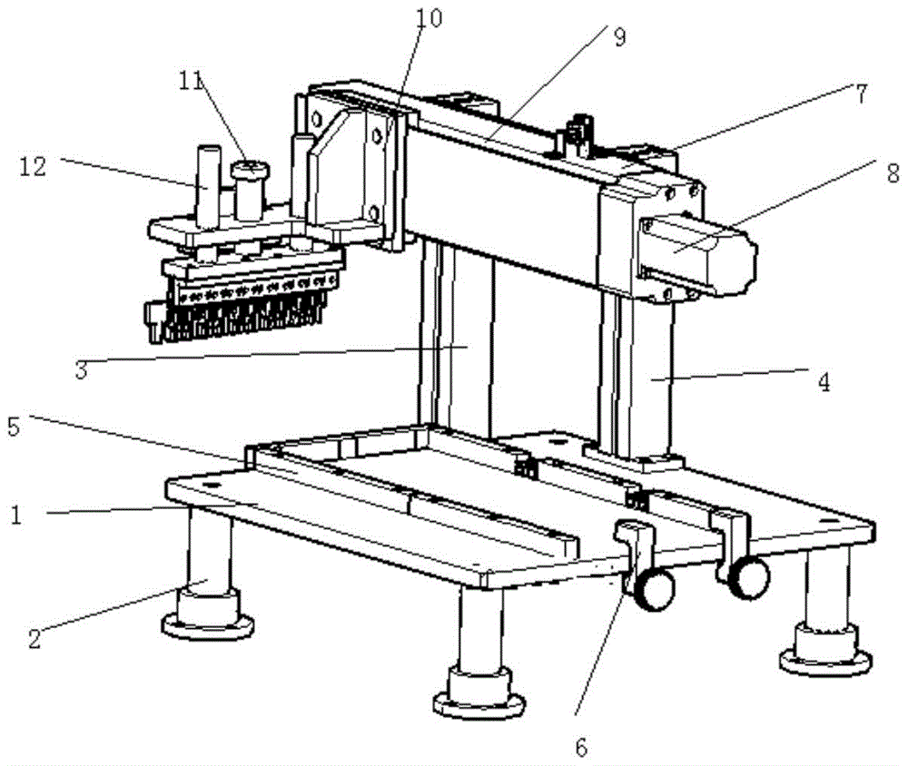
[0015] Such as figure 1 As shown, a precision crimping machine is characterized in that a support column 2 is provided under the base 1, a first column 4 is placed on the base 1, and there is a gap between the first column 4 and the second column 3 on the ground. A connector 7 is connected, the first column 4 and the second column 3 are provided with longitudinal slide rails, the back of the connector is provided with a longitudinal slider, and the front of the connector 7 of the motor is provided with a horizontal slider 10, a horizontal The slide rail 9 and the limit device, the connecting piece 7 is connected with the crimping device and the first motor 8, the first motor 8 drives the connec...


PUM


Abstract

The invention discloses a precision press-connection machine. The precision press-connection machine is characterized by comprising a base; supporting columns are arranged below the base; a first stand column is arranged on the base, and a connecting part is connected between the first stand column and a second landing stand column; the obverse side of the connecting part is provided with a transverse sliding block, a transverse sliding rail and a limiting device; the first stand column and the second stand column are each provided with a longitudinal sliding rail; the reverse side of the connecting part is provided with a longitudinal sliding block; the connecting part is connected with a press-connection device and a first motor; the press-connection device comprises a press-connection plate, a guide column and a second motor; the press-connection plate is provided with press-connection heads with different heights; the base is provided with a positioning device; a controller is connected with the first motor and a second motor workpiece. The precision press-connection machine can punch holes with different depths and in different shapes through the press-connection heads with the different heights at a time, the working efficiency is high, the movement frequency of workpieces is reduced, errors are avoided, and therefore the press-connection accuracy can be guaranteed.

Description

technical field [0001] The invention relates to the technical field of crimping equipment, in particular to a precision crimping machine. Background technique [0002] The traditional crimping machine takes up a lot of space and the working space is small, and because of the unreliable positioning of the workpiece, it often happens that the workpiece passes during the pressing process, causing the pressing position to deviate and affecting the product quality, and it is usually a single crimping joint. The production efficiency is low. When multiple stations need to be pressed, the position of the workpiece must be adjusted frequently. Repeated positioning of the workpiece will cause errors in the positioning of the workpiece, and a large deviation will inevitably be formed in the crimping position. Moreover, the die drives the press. When the connector moves down until it touches the workpiece, the crimping connector often deviates unpredictably relative to the workpiece, a...

Claims


Application Information

Patent Timeline
Patent Type & Authority Patents(China)
IPC IPC(8): B21D39/00B21C51/00
Inventor 尹太阳
Owner 长沙礼恩派拉线工业有限公司
Learn More