
Bottom injection pouring system and its laying method

A pouring system and bottom-injection technology, which is used in casting molding equipment, metal processing equipment, casting molds, etc., can solve the problems of impurities that are not easy to float, difficult to handle, and affect the quality of castings.

Active Publication Date: 2017-09-26
KOCEL STEEL
View PDF7 Cites 1 Cited by
  • Summary
  • Abstract
  • Description
  • Claims
  • Application Information

AI Technical Summary

Problems solved by technology

[0003] This method has been used for a long time in the production of steel castings, and the application technology is very mature. However, this method also has certain defects. The main performance is that in the bottom casting system, the molten steel will flow out from the sliding nozzle at the bottom of the ladle. Mixed with some residual drainage sand and oxide slag produced at the nozzle, these impurities will follow the first molten steel into the pouring system, and finally flow into the cavity, thus affecting the quality of some castings with complex structures that are not easy to scum, especially some ribs For steel castings with many plates and grooves, due to the poor fluidity of molten steel, impurities are not easy to float up, causing these impurities to all adhere to these small and critical parts, subsequent processing is difficult, and it is easy to cause the casting to be scrapped as a whole

Method used


Image

  • Bottom injection pouring system and its laying method
  • Bottom injection pouring system and its laying method
  • Bottom injection pouring system and its laying method

Examples


Embodiment Construction

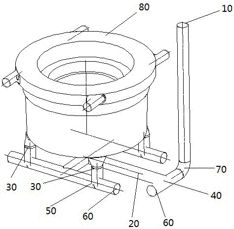
[0017] see Figure 1 to Figure 3 , The bottom pouring gating system includes a sprue 10 , a runner 20 and an inrunner 30 .

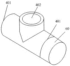
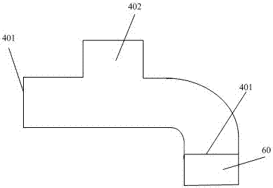
[0018] The inlet end of the sprue 10 is used to connect the sprue basin, and the outlet end of the sprue 10 is connected with the runner 20. The runner 20 is a channel vertical to the sprue 10 and arranged horizontally. The runner 20 In order to connect the passage between the sprue 10 and the ingate 30 to accommodate the flow of molten steel, the inlet end of the runner 20 is connected to the outlet end of the sprue 10, and the outlet end of the runner 20 is connected to the ingate The inlet end of the runner 30 is connected, the outlet end of the ingate 30 is used to communicate with the mold cavity 80 to be poured, and the outlet end of the sprue 10 and the inlet end of the runner 20 are connected by the first T-shaped runner 40 , the first T-shaped runner 40 is a three-way porcelain tube including two horizontal ports 401 and one vertical port 402, ...


PUM


Abstract

A bottom-sprue gating system, comprising a sprue, a runner, and an inner runner, the inlet end of the sprue and the outlet end of the runner are connected by a first T-shaped runner, and the present invention adopts The first T-shaped runner, which is similar to the traditional three-way porcelain pipe, but the horizontal end is blocked by a metal blocking plate. The function of the metal blocking plate is After entering the T-shaped porcelain tube, it is quickly chilled when it touches the metal blocking plate, and condenses into a shell, thereby fixing the impurities on the side of the T-shaped runner with the metal blocking plate, ensuring that the subsequent clean molten steel flows Impurities will no longer be involved in the cavity, so that it can effectively solve the shortcomings of the poor quality of the first molten steel and the shortcomings of impurities generated by the scouring of molten steel in the pouring system, and ensure the pure quality of molten steel flowing into the cavity, thereby Improve casting quality. The invention also provides a laying method of the bottom pouring pouring system.

Description

technical field [0001] The invention relates to the technical field of pouring systems for steel castings, in particular to a bottom pouring pouring system and a laying method thereof. Background technique [0002] At present, large and medium-sized steel castings basically use the bottom pouring system to pour the product. The bottom pouring system is a pouring system in which molten metal flows from the bottom of the casting into the cavity of the mold. This method fills the mold smoothly. The impact force on the sand core is small, and the molten metal is less oxidized. It is especially suitable for the production of large and medium-sized steel castings, and can significantly improve the quality of casting products. [0003] This method has been used for a long time in the production of steel castings, and the application technology is very mature. However, this method also has certain defects. The main performance is that in the bottom casting system, the molten steel w...

Claims


Application Information

Patent Timeline
Patent Type & Authority Patents(China)
IPC IPC(8): B22C9/08
Inventor 马涛何启良杨建唐钟雪
Owner KOCEL STEEL
Learn More