
Eureka
For R&D, Eureka makes reading and utilizing patents & technical documents easy.
Eureka AIR
Designed for self-driven R&D workflows. Generate viable solutions, solve complex R&D challenges, empower your innovation with AI.

Eureka Materials
Designed for material experts only. Revolutionize your material R&D, from search, analyze, to developing new materials.

TechResearch
Generate reliable direction feasibility study reports for your R&D in just a few steps.

TechSeek
Discover and master advanced knowledge NOW. Basics, ideas, possibilities, all at once.

TechMind
As an expert in R&D Theories, TechMind can generates customized viable solutions instantly.

TechRisk
Analyze your overall solution with one click, know your potential R&D risks in advance.

TechMonitor
Get weekly tech updates, stay abreast of the latest tech innovations and key insights.
Apparatus and method for online testing numerical control lathe and intelligently compensating cutter abrasion
A tool wear, CNC lathe technology, applied in the field of CNC lathes, can solve the problems of excessive compensation, inaccurate tool compensation methods, insufficient compensation, etc., to achieve the effect of ensuring measurement accuracy
- Summary
- Abstract
- Description
- Claims
- Application Information
AI Technical Summary
Problems solved by technology
Method used
Image

Examples
Embodiment 1
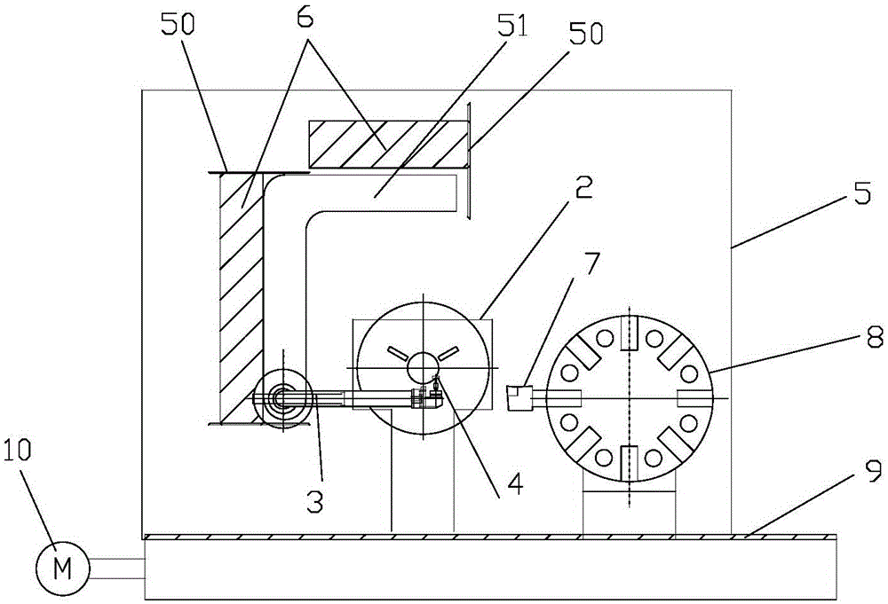
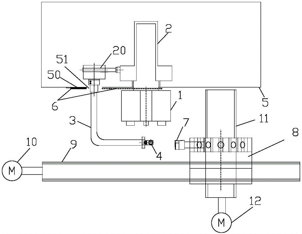
[0035] Such as Figure 1 to Figure 4 The shown online detection and intelligent compensation tool wear device for CNC lathe includes: measuring arm mount 2, measuring arm 3, tool tip contact sensor 4, measuring arm barrier 5, window 6 and data processing unit.
[0036] The measuring arm mounting seat 2 is arranged behind the self-centering chuck 1 of the machine tool. The self-centering chuck 1 is used to clamp the workpiece. The measuring arm mounting seat 2 has a mounting pin 20 . The measuring arm 3 is rectangular, one end of the measuring arm 3 is rotatably connected to the measuring arm mount 2 through the mounting pin 20, and the other end has a tool tip contact sensor 4, and the tool tip contact sensor 4 has a measuring tool 7 in the X direction and Tetrahedral probe in the Z direction. The working position of the measuring arm is that the four faces of the four-sided probe of the tool tip contact sensor 4 are in a vertical state, and the tool tip contact sensor 4 is l...
Embodiment 2
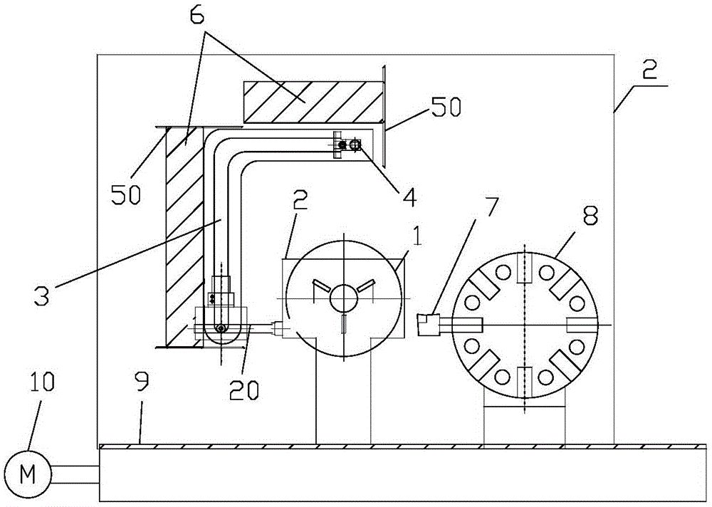
[0048] Such as Figure 5 As shown, the difference between embodiment 2 and embodiment 1 is that the measuring arm barrier 5 is a baffle plate, which reduces the material consumption and can also isolate iron filings and cutting fluid from the measuring arm 3 .
[0049] The online detection and intelligent compensation control flow charts of Embodiments 1 and 2 of the present invention are as follows Image 6 As shown, the position data of the tool 7 measured last time in the X and Z directions are defined as reference data, and the position data of the tool 7 measured this time in the X and Z directions are defined as actual measurement data. Comparing the two data, if there is a difference in the position data of the tool 7 in the X direction, the CNC lathe will automatically compensate according to the difference; The same is true for the compensation control method.
[0050] Timing compensation and fixed piece compensation are to set a constant compensation value, such as...
PUM
 Abstract
Description
Claims
Application Information
 - R&D Engineer
- R&D Manager
- IP Professional
- Industry Leading Data Capabilities
- Powerful AI technology
- Patent DNA Extraction
Browse by: Latest US Patents, China's latest patents, Technical Efficacy Thesaurus, Application Domain, Technology Topic, Popular Technical Reports.
© 2024 PatSnap. All rights reserved.Legal|Privacy policy|Modern Slavery Act Transparency Statement|Sitemap|About US| Contact US: help@patsnap.com