a grabbing device

A grasping device and gripper technology, applied in the field of grasping devices, can solve the problems of broken hooks, heavy weight, and inability to achieve the degree of intelligence.

Active Publication Date: 2016-08-24
BOZHON PRECISION IND TECH CO LTD
View PDF6 Cites 0 Cited by
  • Summary
  • Abstract
  • Description
  • Claims
  • Application Information

AI Technical Summary

Problems solved by technology

However, for products in some special fields, the degree of intelligence we need cannot be achieved when grasping, transporting, and installing
For example: when the hook of product A needs to be inserted into the card slot of product B, the traditional method is to connect the two products manually. If automatic equipment is used, it is difficult to connect the two products. The main reason is that The hook can be firmly inserted into the card slot. The size of the hook is very close to the size of the slot. Even, the head of the hook is slightly larger than the size of the slot.
Therefore, when there is a slight deviation in the positioning of the hook and the slot, the card will not be in place and the hook will break.
Furthermore, some products that need to be picked up have very strict appearance requirements, and when the products are grabbed by automatic equipment such as manipulators, the appearance of the products is easy to be scratched
Some companies use methods such as wrapping products with soft materials to achieve this, but this method cannot fundamentally solve the problem of product damage, especially for some metal products, which are large in size and weight, and the effect of wrapping metal products is not obvious. It is easy to cause the soft wrap to be damaged
When there is a deviation between the grabbing point of the robotic arm and the point to be grabbed of the product, the gripper on the arm will touch a place that should not be touched, which will cause a lot of damage to the product

Method used


Image

  • a grabbing device
  • a grabbing device
  • a grabbing device

Examples


Embodiment Construction

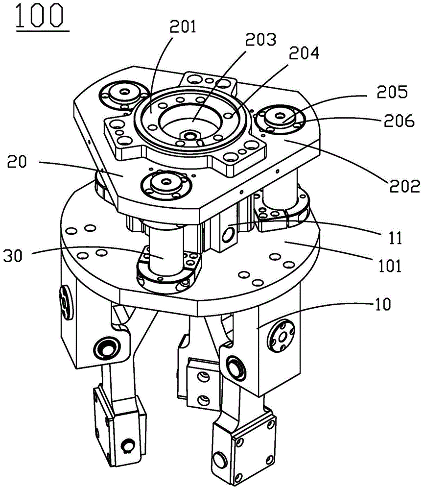
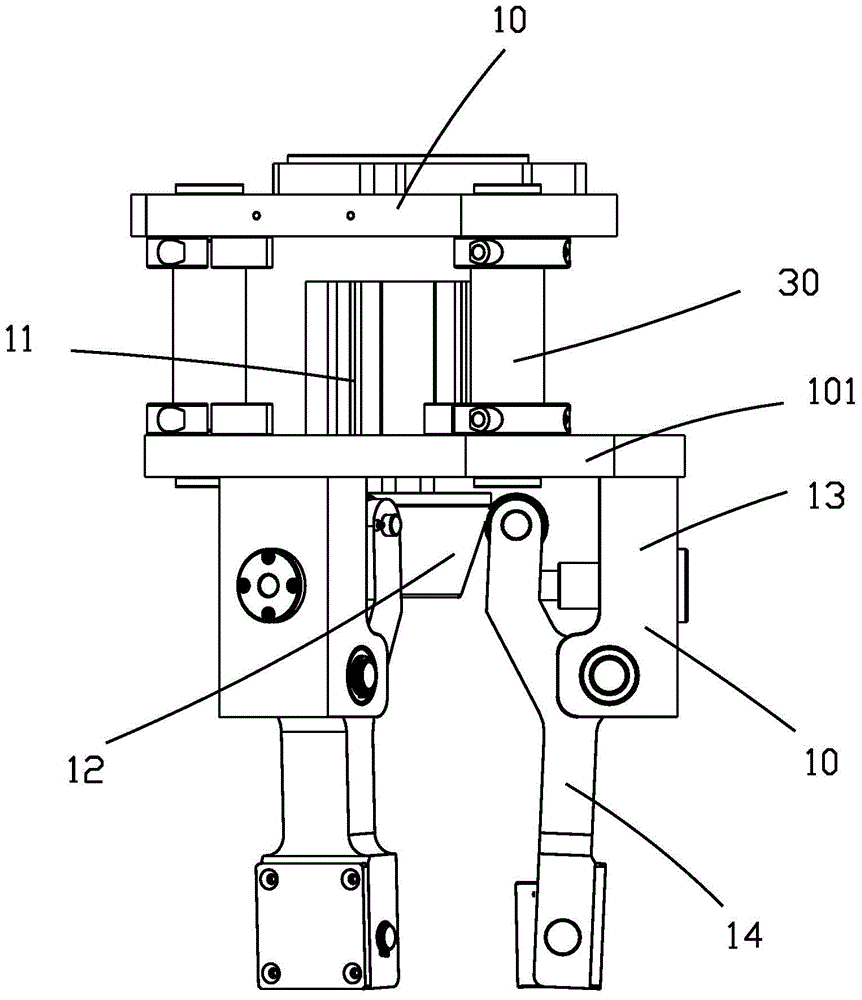
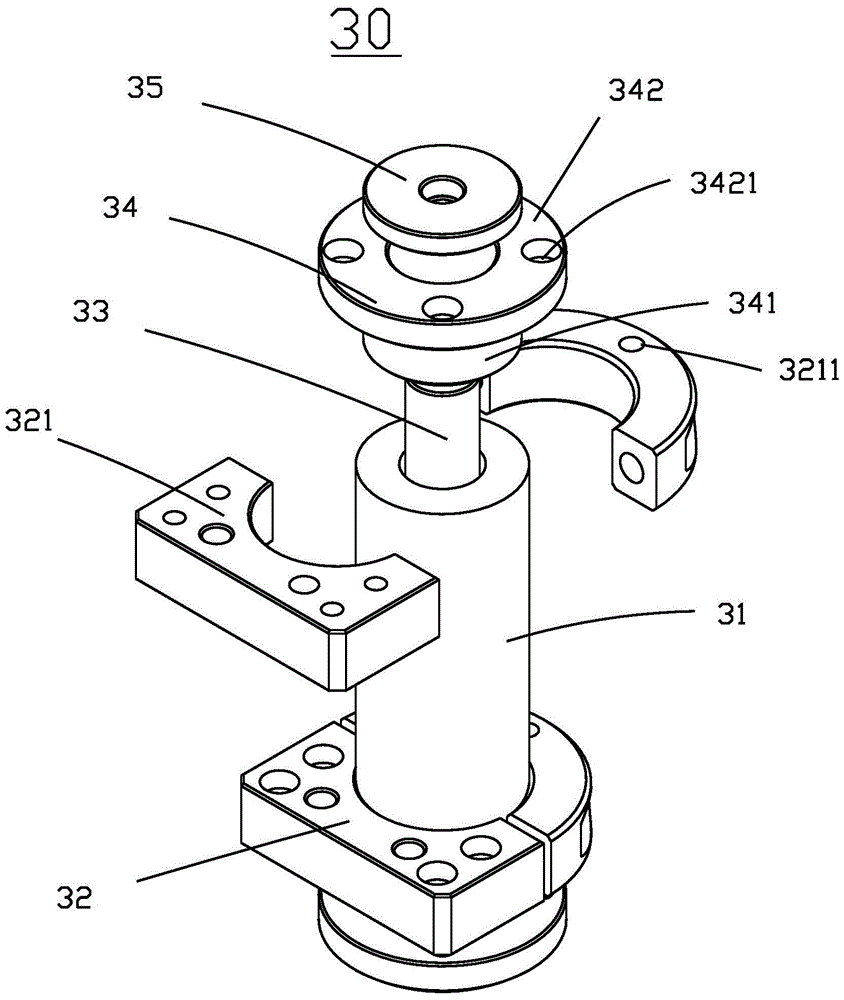
[0024] see Figure 1 to Figure 9 As shown, the present invention discloses a grasping device 100 , which includes a connecting component 20 , a jaw component 10 and a floating component 30 located between the connecting component 20 and the clamping jaw component 10 .

[0025] Such as figure 1 , figure 2 As shown, the connecting assembly 20 includes a connecting plate 201 for connecting with a moving arm (not shown) and a fixing plate 202 for installing the connecting plate 201 . The connecting plate 201 and the fixed plate 202 are installed in parallel with each other, the center of the fixed plate 202 and the connecting plate 201 is provided with a central hole 203 for installing the mobile arm, and a number of fixed holes 204 are arranged around the central hole 203 of the connecting plate 201. Used to assist in immobilizing the moving arm. A plurality of mounting holes 205 are defined around the fixing plate 202 . The installation hole 205 is used for the floating ass...


PUM


Abstract

The invention discloses a grabbing device. The grabbing device is provided with a clamping jaw assembly used for grabbing a product. The clamping jaw assembly comprises a fixed plate, a driving device mounted on the fixed plate, and a clamping jaw used for grabbing the product. The clamping jaw is provided with a plurality of clamping arms. Each clamping arm is provided with a storing hole located at the tail end of the clamping arm, a containing groove concave inwards from one surface of the clamping arm and at least one containing hole extending forwards from the containing groove, wherein the storing hole is communicated with the containing groove. The clamping jaw further comprises second elastic pieces contained in the containing holes respectively, baffles mounted on the clamping arms and abutted against the second elastic pieces, rotary shafts penetrating through the storing holes and clamping blocks which are mounted on the rotary shafts and contained in the containing grooves. The clamping arms and the product can be adjusted through the second elastic pieces, and the situation that the clamping of the product by the clamping blocks is too stiff, the product is damaged through collision is avoided.

Description

technical field [0001] The invention relates to the field of mechanical devices, in particular to a grabbing device. Background technique [0002] In the prior art, automation equipment is more and more popular in various fields. For different technical fields, various products try to replace manual functions with automated products. However, when grabbing, transporting, and installing products in some special fields, it cannot achieve the degree of intelligence we need. For example: when the hook of product A needs to be inserted into the card slot of product B, the traditional method is to connect the two products manually. If automatic equipment is used, it is difficult to connect the two products. The main reason is that The hook can be stably inserted into the slot, and the size of the hook is very close to that of the slot, and even the head of the hook is slightly larger than the slot. Therefore, when there is a slight deviation in the positioning of the hook and th...

Claims


Application Information

Patent Timeline
Patent Type & Authority Patents(China)
IPC IPC(8): B25J15/10
Inventor 吕绍林杨愉强吴小平孙庆邓瑞林姚照荣
Owner BOZHON PRECISION IND TECH CO LTD
Why Eureka
Try Eureka