A material head device for automatic glass tube clamping of automatic bottle feeding machine

A glass tube, automatic technology, applied in glass forming, glass re-forming, glass manufacturing equipment, etc., can solve the problems of glass scratching hands, large loss of workers, and low degree of automation.

Active Publication Date: 2018-04-27
湖北利康医用材料股份有限公司
View PDF5 Cites 0 Cited by
  • Summary
  • Abstract
  • Description
  • Claims
  • Application Information

AI Technical Summary

Problems solved by technology

[0002] At present, there are mainly two types of bottle-making machines used in the bottle-making industry: imported and domestic, but the two types of bottle-making machines generally have defects of low automation; for example, domestic bottle-making machines need to manually clamp the glass tube material head , Workers operate too close to the machine, easily cut hands by glass, hurt head and eyes, etc.; high temperature is difficult to adapt to, high risk, high loss of workers; this kind of operation is not only labor-intensive and time-consuming, but also efficient Low
At present, the domestic glass control bottle machine adopts manual operation in the tube continuation and intubation operation. The automatic tube loading machine that has appeared in the market in recent years has the defect that after the intubation tube enters the tube delivery jacket, the front end of the first glass bottle needs to be clamped manually. The glass tube material head, and then the rear end of each glass tube needs to be manually taken out of the glass tube tail material from the pipe delivery jacket; these two operation methods are not only labor-intensive, but also highly dangerous and inefficient

Method used


Image

  • A material head device for automatic glass tube clamping of automatic bottle feeding machine

Examples


Embodiment Construction

[0008] The present invention will be further described below in conjunction with the accompanying drawings and embodiments.

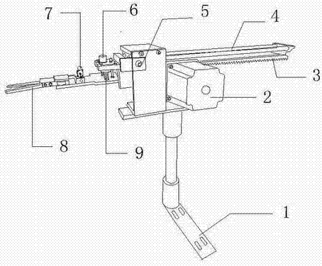
[0009] exist figure 1 Among them, the L-shaped support base 1 and the stepping drive motor 2 are connected to the supporting base plate, and the stepping drive motor 2 is connected to the rack 3 for back and forth transportation. The left side of the L-shaped support base 1 is the same as the base plate. The position is connected with the U-shaped board, an infrared sensor switch 5 is installed on the U-shaped board, the precision guide shaft 4 is fixed on the U-shaped board with a sleeve, the fixed module of the precision guide shaft 4 is connected with the rack 3 as a whole, and is used for Back and forth conveying prepares for the V-shaped clamping shear 8 clamping action; then the V-shaped clamping shear 8 is connected with the push-pull electromagnet 6 and the spring connector 9, which is used for the overall instantaneous displacement, and the tub...


PUM


Abstract

The invention relates to the field of an automatic bottle-upper machine, and relates to a material head device used for automatically clamping glass tubes of the automatic bottle-upper machine. It is characterized in that the L-shaped support base is connected with the stepping drive motor on the supporting base plate, and the stepping drive motor is connected with the rack. The U-shaped plate is equipped with an infrared sensor switch, and the precision guide shaft is fixed on the U-shaped plate with a sleeve. On the board, the precision guide shaft fixing module and the rack are connected as a whole, and the V-shaped clamping scissors are connected with the upper push-pull electromagnet and the spring connector; the V-shaped clamping scissors are processed by two front ends into a V The shape of the iron bar, and the tail end is formed with a gear occlusal shape, and the push-pull electromagnet is fixed on the connecting mother board of the V-shaped clamping scissors. Due to the adoption of this technical solution, it can optimize the automatic production process, reduce manual operation procedures and labor intensity, improve work efficiency; avoid production safety accidents, replace consumable tool clamps, and save manpower and financial resources.

Description

technical field [0001] The invention relates to the field of an automatic bottle-upper machine, and relates to a feeder device for automatically clamping glass tubes of the automatic bottle-upper machine. Background technique [0002] At present, there are mainly two types of bottle-making machines used in the bottle-making industry: imported and domestic, but the two types of bottle-making machines generally have defects of low automation; for example, domestic bottle-making machines need to manually clamp the glass tube material head , Workers operate too close to the machine, easily cut hands by glass, hurt head and eyes, etc.; high temperature is difficult to adapt to, high risk, high loss of workers; this kind of operation is not only labor-intensive and time-consuming, but also efficient Low. At present, the domestic glass control bottle machine adopts manual operation in the tube continuation and intubation operation. The automatic tube loading machine that has appea...

Claims


Application Information

Patent Timeline
Patent Type & Authority Patents(China)
IPC IPC(8): C03B23/045
Inventor 程健
Owner 湖北利康医用材料股份有限公司
Why Eureka
Try Eureka