Cross cementing method without occupying the wellhead

A technology for cementing and surface casing, which is used in wellbore/well components, earth-moving drilling, sealing/packing, etc. The effect of casing hanging on the wall, improving aging and realizing wellbore integrity

Active Publication Date: 2018-01-26
CHINA NAT OFFSHORE OIL CORP +1
View PDF10 Cites 0 Cited by
  • Summary
  • Abstract
  • Description
  • Claims
  • Application Information

AI Technical Summary

Problems solved by technology

[0002] In the process of offshore oil exploration and development, the cementing of the 20″ surface casing of the sub-type batch drilling adopts the inner string to insert the cement. Since the inner string is inserted and cemented, the wellhead operation must be occupied, and the surface cementing operation time is increased due to the injection of cement. The volume and the gap between the casing and the wellbore annulus are large, the consumption of cement slurry is large, and the cementing operation time is long, which is not conducive to improving the timeliness of offshore drilling
Disadvantages of inner string insertion cementing: (1) The operation time is long, and there are limited means to deal with complex situations in the casing and wellbore annulus during the running of the inner string; (2) Although the wellhead operation is simple, once the wellhead casing occurs The fall of the pipe will be catastrophic; (3) the casing is filled with seawater, and there is a greater risk in the insertion and sealing and sealing operations
However, when using blind cementing, there are many disadvantages of casing hanging on the wall, slugging phenomenon, poor cementing quality, low replacement efficiency, empty replacement or high cement plug

Method used


Image

  • Cross cementing method without occupying the wellhead
  • Cross cementing method without occupying the wellhead

Examples


Embodiment Construction

[0019] In order to enable those skilled in the art to better understand the technical solution of the present invention, the present invention will be described in further detail below in conjunction with the accompanying drawings and specific embodiments. And the features in the embodiments can be combined with each other.

[0020] The cross cementing method without occupying the wellhead of the present invention comprises the following steps:

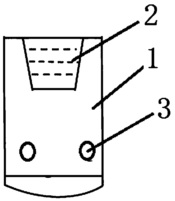
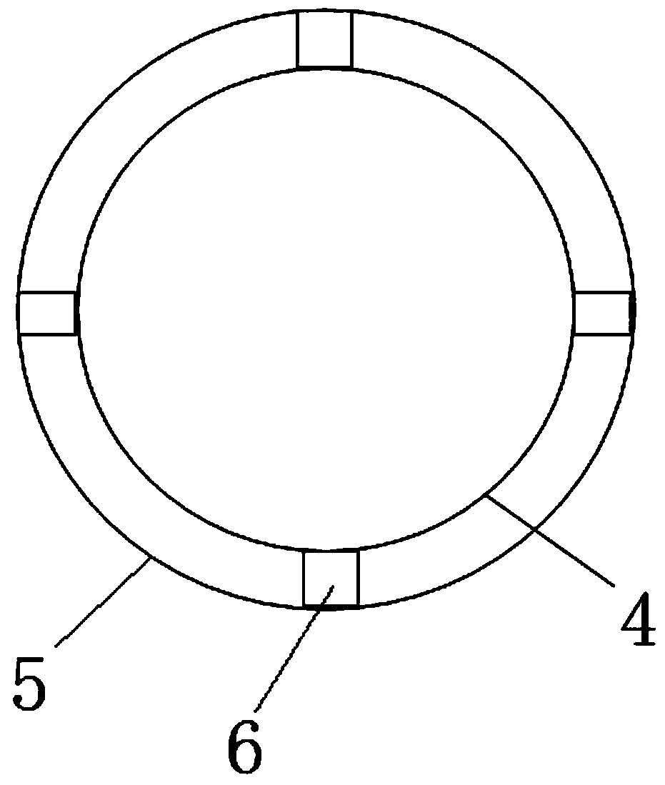
[0021] S1. Connect the casing floating shoe 1 at the lower end of the 20″ surface casing 4. The structure of the casing floating shoe is as follows figure 1 As shown, the casing float shoe 1 is provided with a plurality of evenly distributed side outlet holes 3 on the side wall below the float shoe check valve seat 2, and by setting the side outlet holes 3 on the side wall of the casing float shoe 1 , the flow channel formed by the side outlet hole can be used to ensure the cementing operation, and the casing float shoe plays the dua...


PUM


Abstract

The invention discloses a cross well cementation method without occupying a well mouth. The method comprises the following steps: (S1) the lower end of a 20" surface layer sleeve is connected with a sleeve float shoe, wherein the sleeve float shoe is provided with a side outlet hole on the side wall below a float shoe check valve base; (S2) the 20" surface layer sleeve is directly descended to a base, and is fixed in center through righting blocks in the well mouth; (S3) a drilling table inverts and swings the 20" surface layer sleeve in the position of conveniently connecting with a circulating head of the 20" sleeve below a turntable to shift a derrick to a next well position to perform the cross well cementation operation without occupying the well mouth in the well mouth area; and (S4) the return condition is observed in the well cementation period; and after cement is returned out from the well mouth, the replacement operation is immediately switched to finish the well cementation. The method finishes the well cementation operation by connecting the circulating head in the well mouth area, finishes the 20" surface layer sleeve well cementation operation without occupying well mouth time, finishes the all-well-section sealing by returning cement to the well mouth according to high-temperature and high-pressure shaft completeness requirements, and guarantees the integration of the 20" sleeve and a 30" pile pipe to realize the shaft completeness.

Description

technical field [0001] The invention belongs to the technical field of well drilling, and in particular relates to a well cementing operation method. Background technique [0002] In the process of offshore oil exploration and development, the cementing of the 20″ surface casing of the sub-type batch drilling adopts the inner string to insert the cement. Since the inner string is inserted and cemented, the wellhead operation must be occupied, and the surface cementing operation time is increased due to the injection of cement. The volume and the gap between the casing and the wellbore annulus are large, the consumption of cement slurry is large, and the cementing operation time is long, which is not conducive to improving the efficiency of offshore drilling. The disadvantages of the inner pipe string insertion cementing: (1) The operation time is long, If there are complex situations in the casing and wellbore annulus during running into the inner string, there are limited m...

Claims


Application Information

Patent Timeline
Patent Type & Authority Patents(China)
IPC IPC(8): E21B33/13
Inventor 李中黄熠邓诚李炎军罗东辉肖伟张万栋汪俊锋朱新华林四元张可刘国栋
Owner CHINA NAT OFFSHORE OIL CORP
Why Eureka
Try Eureka