
Gear box elastic support component of wind turbine generator set

A wind turbine, elastic support technology, applied in wind turbine components, wind turbines, engines, etc., can solve the problems of high production cost and inspection cost, heavy weight, and large volume of elastic support components.

Inactive Publication Date: 2015-12-02
JIANGSU TIEKE NEW MATERIAL CO LTD
View PDF4 Cites 5 Cited by
  • Summary
  • Abstract
  • Description
  • Claims
  • Application Information

AI Technical Summary

Problems solved by technology

[0002] Traditionally, the elastic support assembly of the gearbox of wind power generation equipment generally includes a U-shaped frame, an upper beam installed on the U-shaped frame, a lower elastic member installed at the center of the U-shaped frame, and an upper elastic member installed at the center of the upper beam. And the U-shaped frame and the upper beam are respectively provided with adjusting bolts that can adjust the upper and lower elastic parts. The traditional structure can play an elastic buffering role well, but due to its unreasonable structural design, the volume of the elastic support assembly It is relatively large and very heavy. The way of casting in the manufacturing process leads to serious waste of materials, large processing volume, high production cost and inspection cost, and low production efficiency.

Method used


Image

  • Gear box elastic support component of wind turbine generator set
  • Gear box elastic support component of wind turbine generator set
  • Gear box elastic support component of wind turbine generator set

Examples


Embodiment 2

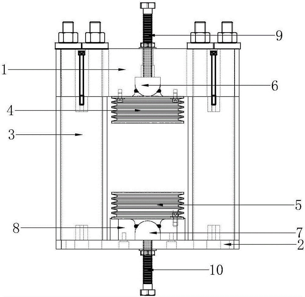
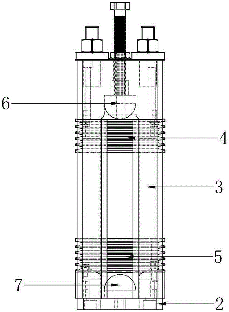
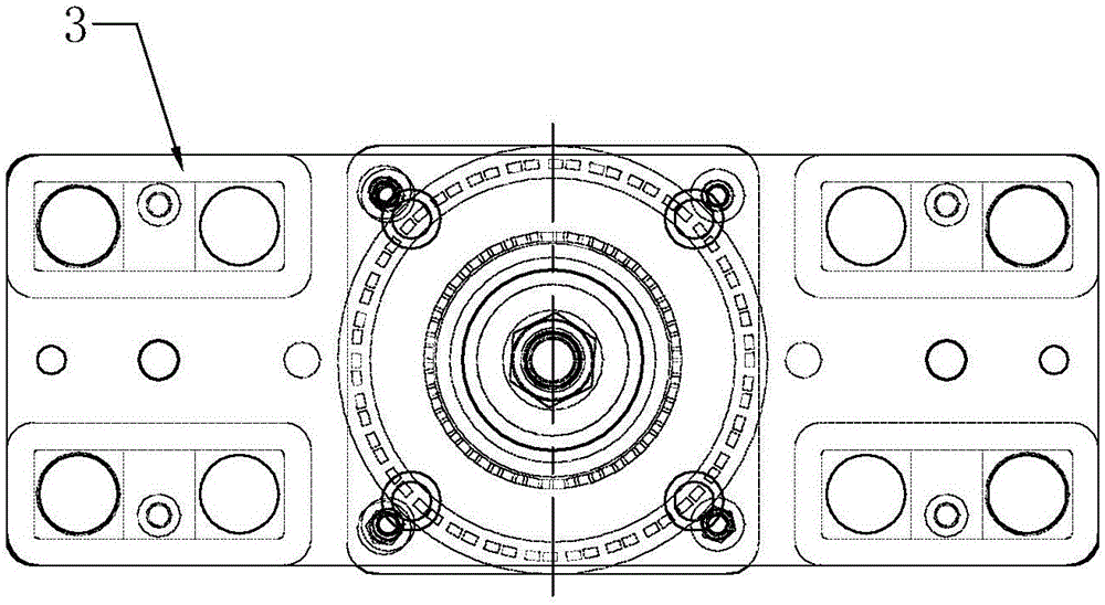
[0021] Such as figure 1 , figure 2 , Figure 4 As shown, the elastic support assembly of the gearbox of the wind turbine generator of the present invention includes an upper base 1 and a bottom plate 2 and two uprights 3 connected between the upper base 1 and the bottom plate 2, such as Figure 4 As shown, the cross-sectional shapes of the outer contours of the two uprights 3 are both rectangular, and at the same time, the two uprights 3 can be set as hollow uprights. At this time, two partitions can be arranged in the two uprights, thereby making the entire upright The cross section is formed into a substantially mesh-shaped structure. When installed, the two uprights 3 are respectively located at the edge of the left and right sides of the upper base 1, and the two uprights respectively penetrate the entire width direction of the side. Through this structural design, The upper seat body 1, the bottom plate 2 and the two uprights 3 constitute a frame structure. The bottom cente...


PUM


Abstract

The invention discloses a gear box elastic support component of a wind turbine generator set. The component comprises an upper base body and a baseplate, wherein a frame structure formed by four stand columns with rectangular sections at four corner parts of the upper base body and the baseplate is connected between the upper base body and the baseplate; an upper elastic piece is arranged in the bottom center of the upper base body; a lower elastic piece is arranged in the upper center of the baseplate; an upper ejector block aligned to the upper elastic piece is arranged above the upper base body; and a lower ejector block aligned to the lower elastic piece is arranged below the baseplate. After the structure is adopted, on the one hand, the structures of the stand columns enable the weight to be light, the material waste is prevented in the machining process, and the cost is saved; and on the other hand, the base and the stand columns are singly arranged, the installation is more convenient when the whole volume is decreased, and the manufacturing cost is further reduced; and in addition, a limiting block is arranged at the upper part of the baseplate, so that the baseplate is thinner to further reduce the whole weight when the installation position can be guaranteed.

Description

Technical field [0001] The invention relates to a component of a gear box of a wind power generation equipment, in particular to an elastic support assembly of a gear box of a wind power generating set. Background technique [0002] Traditionally, the elastic support assembly of the gearbox of wind power generation equipment generally includes a U-shaped frame, an upper beam installed on the U-shaped frame, a lower elastic part installed in the center of the U-shaped frame, and an upper elastic part installed in the center of the upper beam. In addition, the U-shaped frame and the upper beam are respectively provided with adjusting bolts capable of adjusting the upper and lower elastic parts. The traditional structure can play a good elastic buffering effect, but due to the unreasonable structural design, the volume of the elastic support assembly It is relatively large and heavy. The method of casting and molding in the manufacturing process causes serious material waste, large ...

Claims


Application Information

Patent Timeline
Patent Type & Authority Applications(China)
IPC IPC(8): F03D11/02F03D11/04
CPCY02P70/50
Inventor 朱成顺刘春岐谭飞丁雷贺宝帅
Owner JIANGSU TIEKE NEW MATERIAL CO LTD
Learn More