Refrigerator air return system and method

A technology for air systems and refrigerators, applied in lighting and heating equipment, cooling fluid circulation devices, household appliances, etc., can solve the problems of long air flow, bottom return air congestion, affecting return air efficiency, etc., to improve uniformity and temperature. The uniformity of the air flow is improved, the uniformity of the airflow distribution and the temperature uniformity are improved, and the effect of reducing the local congestion of the airflow

Active Publication Date: 2015-12-02
HEFEI HUALING CO LTD +1
View PDF7 Cites 13 Cited by
  • Summary
  • Abstract
  • Description
  • Claims
  • Application Information

AI Technical Summary

Problems solved by technology

The air duct structure of the existing refrigerators makes the air circulation generally in the form that the air flows out from the upper air outlet of the air duct cover plate, circulates from top to bottom in the entire room, and then flows back to

Method used


Image

  • Refrigerator air return system and method
  • Refrigerator air return system and method

Examples


Embodiment 1

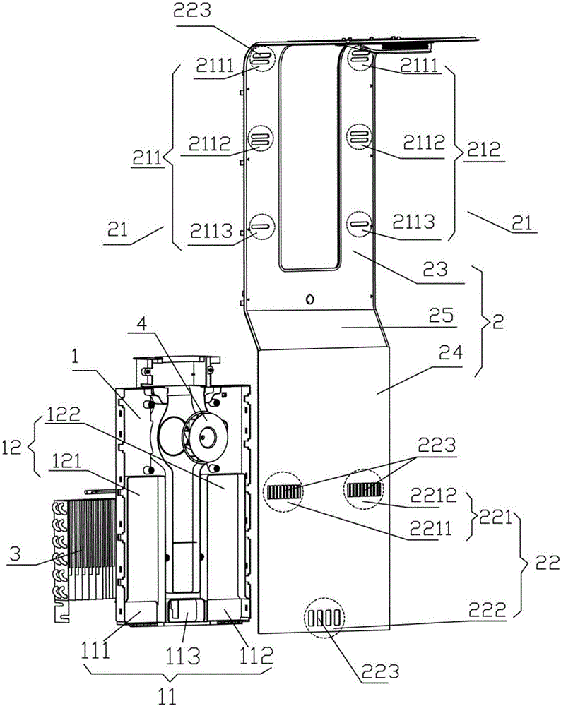
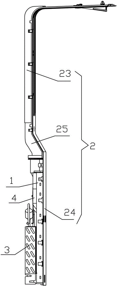
[0042] Such as figure 1 As shown, a refrigerator return air system in this embodiment includes an air duct main body 1, an air duct cover plate 2, a fan 4 and an evaporator 3 arranged on the back of the refrigerator box, and the air duct cover plate 2 covers the refrigerator box body. on the back of the refrigerator, the length of the air duct cover plate 2 is the same as the height of the refrigerator; figure 2 As shown, the air duct main body 1, the air duct cover plate 2 and the evaporator 3 are stacked in sequence to form a layered structure, the air duct main body 1 is clamped between the air duct cover plate 2 and the evaporator 3 in a plate shape, and the fan 4 is fixed Above the air duct main body 1. The air duct cover plate 2 includes an upper half 23 and a lower half 24, the upper half 23 and the lower half 24 are connected by a slant plate 25, the air duct main body 1 and the evaporator 3 are connected with the lower half of the air duct cover plate 2 24 connecte...

Embodiment 2

[0048] On the basis of Embodiment 1, this embodiment is further provided with a return air duct 12 on the air duct main body 1 .

[0049] Such as figure 1 As shown, the return air duct 12 is arranged above the return air duct 11 , and the return air duct 11 communicates with the return air duct 12 . The return air duct 12 is a groove provided on one side of the air duct main body 1, and the groove is in a rectangular parallelepiped structure. The return air duct 12 comprises a first return air duct 121 and a second return air duct 122, and the first return air duct 121 and the second return air duct 122 are symmetrically arranged on both sides of the fan 4; The air return channel 121 is on the same level as the first air return port 2211 and communicates with it, and the second return air channel 122 is on the same level as and communicates with the second air return port 2212 . By setting two return air ducts on the left and right, the air flow is separated into two bundles...


PUM


Abstract

The present invention relates to a refrigerator air return system and method. The air return system comprises an air duct main body disposed at a back part of a refrigerator body, an air duct cover plate, a fan and an evaporator, wherein the air duct main body, the air duct cover plate and the evaporator are superposed in turn to form a laminated structure, the air duct main body is arranged between the air duct cover plate and the evaporator, the fan is fixed above the air duct main body, air return passages are disposed on the air duct main body and are communicated with the evaporator, an air outlet part and a plurality of air return layers are disposed on the air duct cover plate, the air return layers are distributed below the air outlet part, the evaporator and the inside of the refrigerator body are communicated by the air outlet part, and the air return passages and the inside of the refrigerator box are communicated by the air return layers. With horizontal arrangement of the air return layers on the air duct cover plate, airflows inside the refrigerator body flow back to the evaporator in a layered manner, air return flows do not interfere with each other, local blockage of the airflows is reduced, and indoor airflow distribution uniformity and temperature uniformity among refrigerator bodies are raised.

Description

technical field [0001] The invention relates to the technical field of household appliances, in particular to a refrigerator return air system. Background technique [0002] Existing refrigerators usually make the cold air generated by the evaporator enter the freezing chamber and the refrigerating chamber along the air duct to form a circulation by means of a fan. The air duct structure of the existing refrigerators makes the air circulation generally in the form that the air flows out from the upper air outlet of the air duct cover plate, circulates from top to bottom in the entire room, and then flows back to the evaporator from the bottom air return port through the bottom middle air return channel At the bottom, the airflow process is longer and it is easy to cause congestion of the return air at the bottom, which affects the efficiency of the return air. Contents of the invention [0003] The technical problem to be solved by the present invention is to provide a re...

Claims


Application Information

Patent Timeline
IPC IPC(8): F25D17/06
Inventor 陆彭飞吴国富方忠诚
Owner HEFEI HUALING CO LTD
Why Eureka
Try Eureka