Laminated shearing box

A shear box and stacking technology, applied in measuring devices, instruments, vibration testing and other directions, can solve problems such as difficult to reflect the seismic response of soil layers, and achieve the effects of convenient installation and application, improved accuracy, and simple structure

Inactive Publication Date: 2015-12-02
BC P INC CHINA NAT PETROLEUM CORP +2
View PDF6 Cites 15 Cited by
  • Summary
  • Abstract
  • Description
  • Claims
  • Application Information

AI Technical Summary

Problems solved by technology

[0006] The purpose of the present invention is to provide a laminated shear box, which reduces the influence of boundary effects and solves the technical problem that the existing shear box is difficult to reflect the actual seismic response of the soil layer

Method used


Image

  • Laminated shearing box
  • Laminated shearing box
  • Laminated shearing box

Examples


Embodiment approach 1

[0041] Embodiment 1: Roller type; specifically, a rolling groove is fixed on the rectangular steel frame, and the rollers are placed in the rolling groove.

Embodiment approach 2

[0042] Embodiment 2: Ball type; specifically, a chute is fixed on the rectangular steel frame, and balls are placed in the chute.

Embodiment approach 3

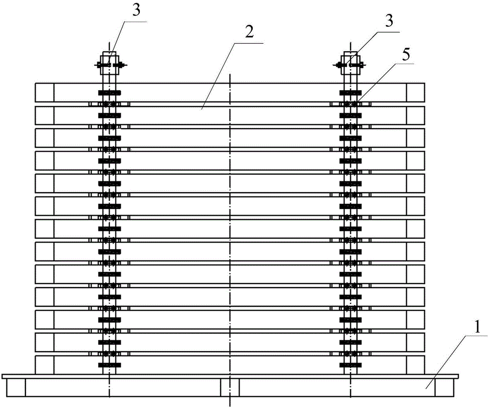
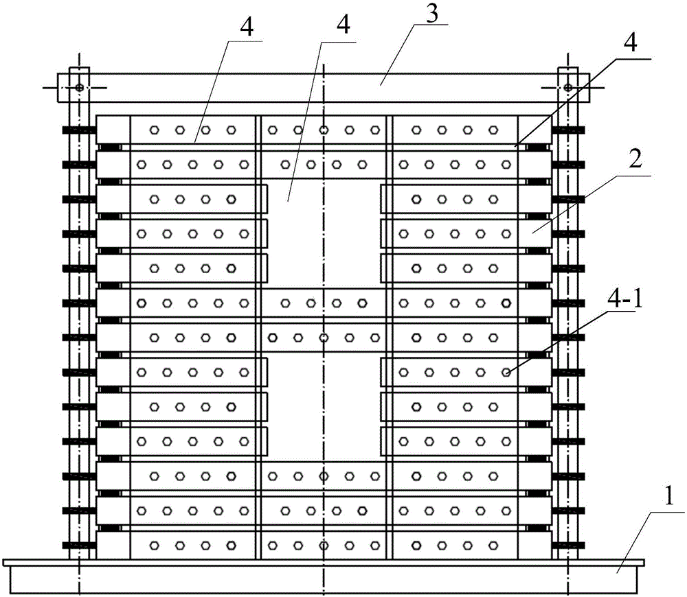
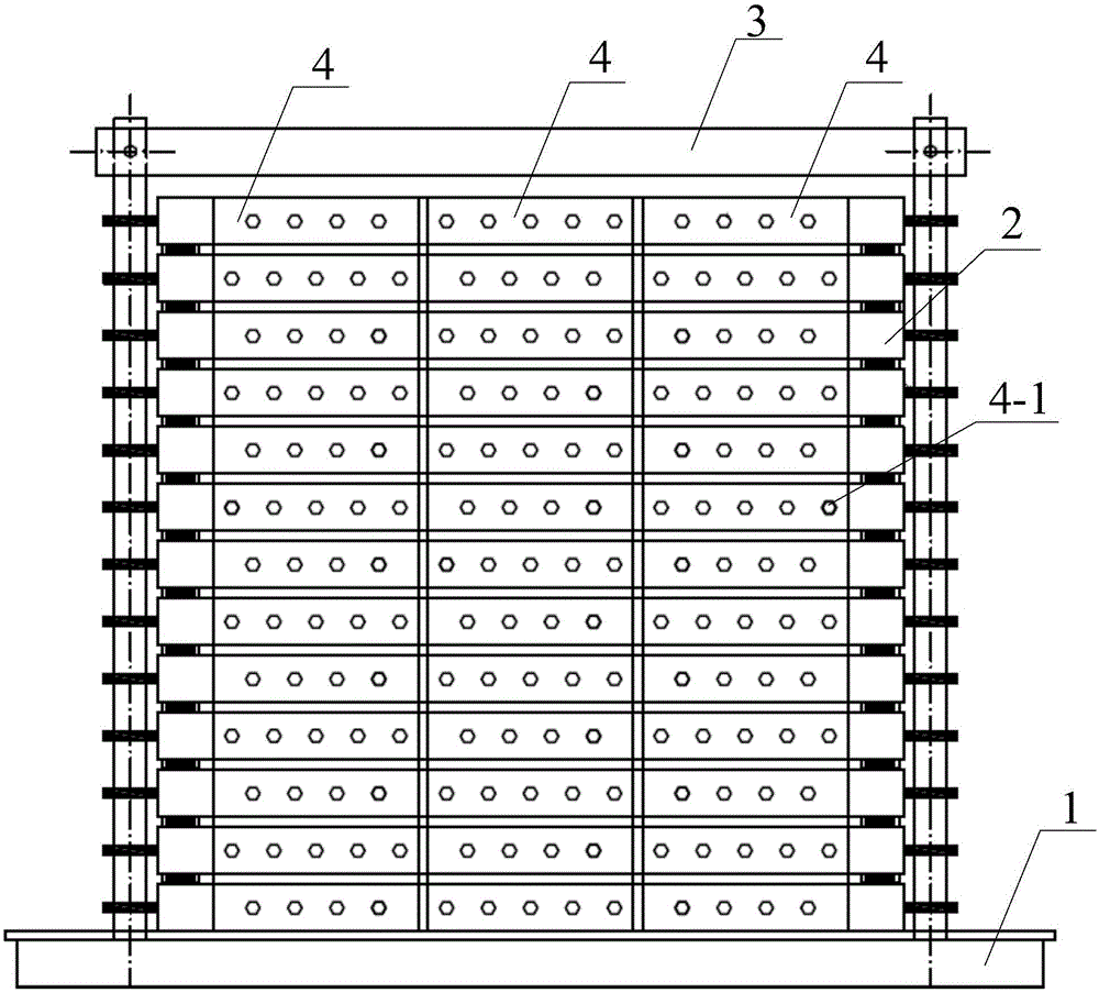
[0043] Implementation Mode Three: Reference Figure 7 As shown, the sliding mechanism 5 includes a guide groove 5-1, a fixing groove 5-2, and a sliding assembly. Specifically, except for the bottom rectangular steel frame, a guide groove 5-1 is fixed at the bottom of each other rectangular steel frame, except The rectangular steel frame on the top layer is fixed with a fixed groove 5-2 on the top of each other rectangular steel frame, and the sliding assembly is arranged in the fixed groove 5-2; when two adjacent layers of rectangular steel frames are stacked, the lower rectangular steel frame The fixing groove 5-2 is inserted into the guide groove 5-1 of the upper rectangular steel frame, and the sliding assembly drives the upper rectangular steel frame to slide along the guide groove 5-1, so that the orientation horizontal relative between two adjacent rectangular steel frames slip. Specifically, each sliding assembly is composed of a fixed shaft 5-3 and one or more deep gr...


PUM


Abstract

The invention discloses a laminated shearing box. The objective of the invention is to solve the technical problem of difficulty to reflect actual seismic responses of soil layers of an existing shearing box. The laminated shearing box comprises a rigid base, a laminated box body, limiting mechanisms and side limiting plates; the rigid base is mounted on a vibration table; the laminated box body is located on the rigid base; the exteriors of two first side surfaces of the laminated box body are provided with the limiting mechanisms; the limiting mechanisms are fixed on the rigid base; the exteriors of two second side surfaces of the laminated box body are provided with the side limiting plates; the first side surfaces are parallel to the vibration direction of the vibration table; and the second side surfaces are vertical to the vibration direction of the vibration table. The laminated shearing box of the invention can be basically consistent with a prototype. With the laminated shearing box adopted, when pipelines buried at different depths are tested under seismic excitation or fault movement simulation, the actual seismic responses of the soil layers can be reflected, and therefore, the accuracy of the seismic tests of oil and gas pipelines can be improved.

Description

technical field [0001] The invention relates to the technical field of seismic tests, in particular to a laminated shear box. Background technique [0002] In the seismic test of oil and gas pipelines, it is necessary to design a container to hold the soil and keep it in a certain shape. Since the prototype soil approximately undergoes shear deformation under earthquake action, an ideal soil container should satisfy the following conditions: it can not only simulate the boundary conditions of the soil correctly, but also correctly simulate the shear deformation of the soil. In fact, the limitation of the soil box boundary to the deformation of the soil, as well as the emission and scattering of waves will have a greater impact on the test results, which is the so-called "model box effect". Therefore, how to reduce the fluctuation reflection of the soil box boundary has become the key and difficult point of the experiment. [0003] In the current shaking table test, the ide...

Claims


Application Information

Patent Timeline
Patent Type & Authority Applications(China)
IPC IPC(8): G01M7/02G01N3/02
Inventor 曹文冉许浩罗小桥张月超邓海峰刘振纹
Owner BC P INC CHINA NAT PETROLEUM CORP
Why Eureka
Try Eureka