
Light sensing structure and manufacturing method thereof

A manufacturing method and light sensing technology, applied in the field of light sensing structures, can solve problems such as difficult process methods, and achieve the effect of solving tolerance problems

Active Publication Date: 2018-06-29
INTERFACE TECH CHENGDU CO LTD +1
View PDF6 Cites 0 Cited by
  • Summary
  • Abstract
  • Description
  • Claims
  • Application Information

AI Technical Summary

Problems solved by technology

When the infrared hole is closer to the metal trace, it will make the sensing film less prone to opening, and a more difficult process method must be adopted

Method used


Image

  • Light sensing structure and manufacturing method thereof
  • Light sensing structure and manufacturing method thereof
  • Light sensing structure and manufacturing method thereof

Examples


Embodiment Construction

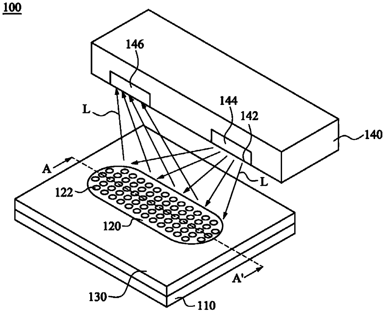
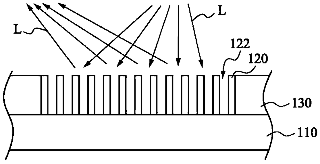
[0032] Next, the present invention will be described in detail with embodiments and accompanying drawings. In the drawings or descriptions, similar or identical parts use the same symbols or numbers. In the drawings, the shape or thickness of the embodiments may be exaggerated for simplification or convenient labeling, and the parts of the components in the drawings will be described in words. It can be understood that elements not shown or described can be in various forms known to those of ordinary skill in the art. This embodiment is illustrated in schematic cross-section of an idealized embodiment (and intermediate structures) of the invention, and reasonable variations in fabrication methods, shapes and / or tolerances will be contemplated by those skilled in the art. Therefore, the embodiments of the present invention should not be construed as limiting the protection scope of the present invention.

[0033] Figure 1A is a perspective view of the photo-sensing structure ...


PUM


Abstract

The invention provides a light sensing structure. The photo-sensing structure includes a transparent substrate, a patterned filter layer, a light-shielding layer and a photo-sensing element. The patterned filter layer is disposed on the transparent substrate, and the patterned filter layer has a plurality of microholes to expose a part of the transparent substrate. The light-shielding layer is disposed on the transparent substrate and surrounds the patterned filter layer. The light sensing element is disposed above the patterned filter layer and the light shielding layer, and has a light emitting surface facing the patterned filter layer. A method for manufacturing a photo-sensing structure is also disclosed herein. Since the photo-sensing structure provided by the present invention does not need to form an infrared hole on the glass cover, it can solve the tolerance problem caused when the glass cover is attached to the sensing film.

Description

technical field [0001] The present invention relates to a photo-sensing structure, in particular to a photo-sensing structure in which a patterned filter layer is formed by using a laser drilling method or a laser engraving method. Background technique [0002] In the current structure of the touch panel, the infrared hole of the general cover glass is made by a method including infrared ink printing, black matrix and laser engraving hole of the ambient light sensor. However, in the fabrication of the infrared sensing film, it is usually necessary to form an opening so that the infrared sensing element can directly contact the surface of the glass cover. When the infrared hole is closer to the metal trace, it will make the sensing film less prone to opening, and a more difficult process method must be adopted. [0003] In addition, since the infrared hole formed on the glass cover must be opposite to the sensing film, the attachment tolerance between the sensing film and th...

Claims


Application Information

Patent Timeline
Patent Type & Authority Patents(China)
IPC IPC(8): G06F3/042
Inventor 黄嘉信
Owner INTERFACE TECH CHENGDU CO LTD
Learn More