
Method of machining a toothed workpiece, machining unit operable to perform the method and machine tool equipped with the machining unit

A technology for processing units and workpieces, applied to components with teeth, metal processing equipment, gear cutting machines, etc., can solve problems such as gear tooth damage, and achieve the effect of tolerance

Inactive Publication Date: 2018-08-31
GLEASON WORKS
View PDF1 Cites 0 Cited by
  • Summary
  • Abstract
  • Description
  • Claims
  • Application Information

AI Technical Summary

Problems solved by technology

[0004] However, experience with methods of the aforementioned kind has shown that the machining of the tooth edges can cause unintentional damage to the gear teeth of the workpiece

Method used


Image

  • Method of machining a toothed workpiece, machining unit operable to perform the method and machine tool equipped with the machining unit
  • Method of machining a toothed workpiece, machining unit operable to perform the method and machine tool equipped with the machining unit
  • Method of machining a toothed workpiece, machining unit operable to perform the method and machine tool equipped with the machining unit

Examples


Embodiment Construction

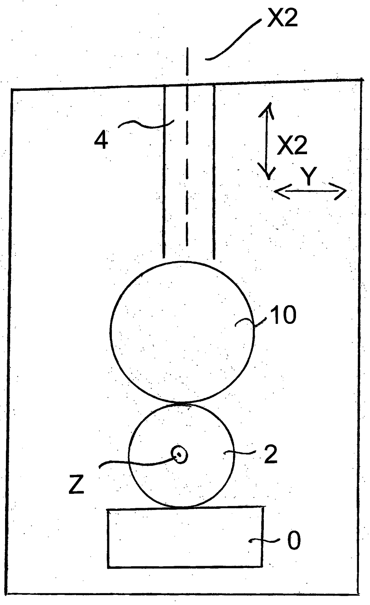
[0035] In the simplified schematic diagram from above, figure 1 Selected portions of machine tool 20 are shown, which are sufficient for an understanding of the invention. In this embodiment, the machine tool 20 is a hobbing machine, the main design of which is known and will not be further explained herein. exist figure 1 Shown in are all hob milling tools (hob 0) whose mobility is defined by the conventional axes of motion required for the machining of gear teeth on blanks mounted in the production of toothed workpieces 2 on the workpiece mandrel. exist figure 1 In what is shown, the workpiece axis Z is oriented orthogonally to the plane of the drawing.

[0036]In this example, the chamfering tool 10 , which can perform a transverse movement along the axis of movement X2 , is arranged on the side of the workpiece 2 diametrically opposite the hob 0 . However, the axis of movement X2 of the chamfering tool can also be oriented at an angle to the axis of the main tool, eg ...


PUM


Abstract

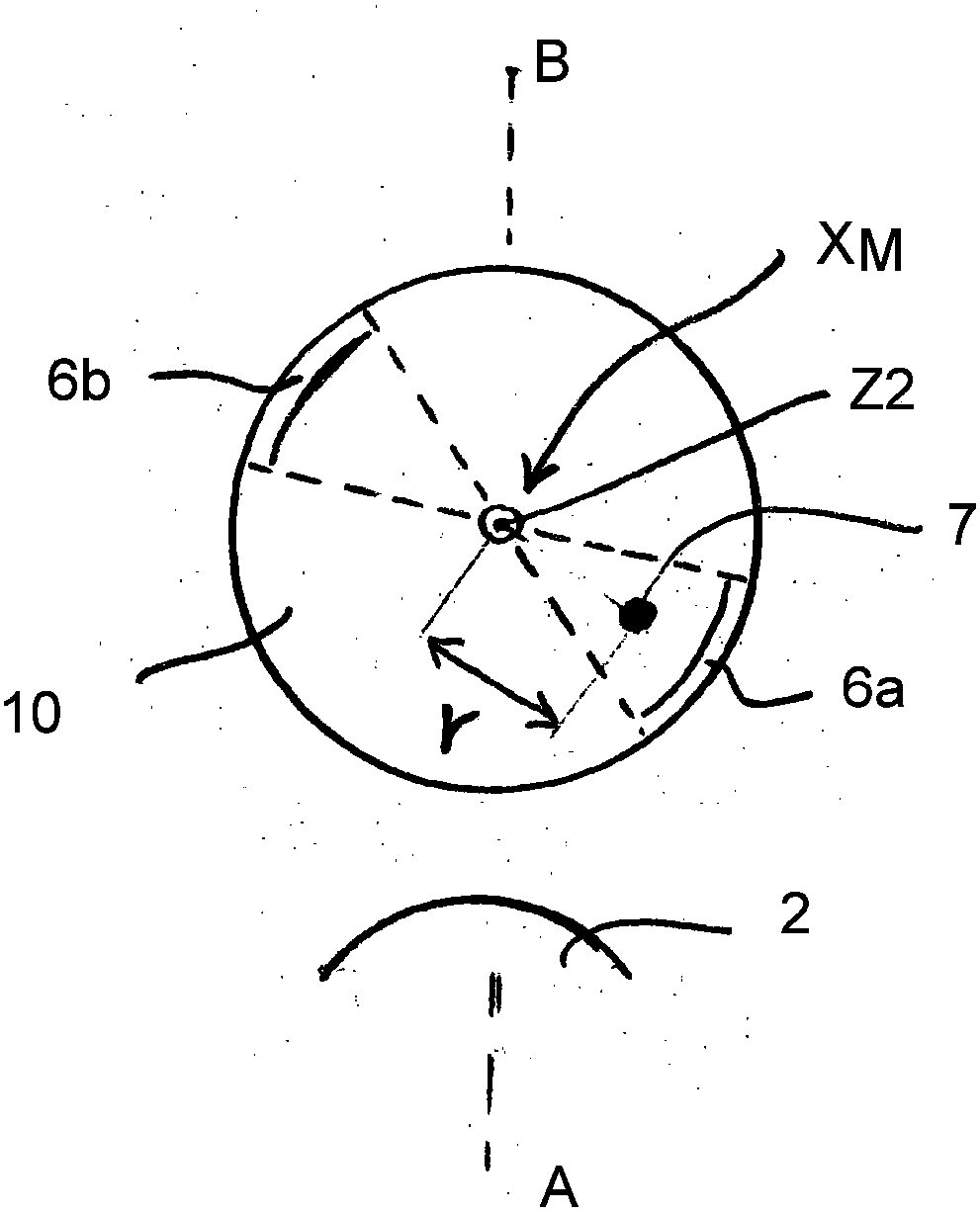
The invention concerns a method for the machining of toothed workpieces, in particular for the plastic reshaping of the tooth edges at the ends of the teeth through a meshing tooth engagement with a tool that is rotatable with free-running mobility about its axis of rotation, in particular a chamfering tool, wherein between the machining of one workpiece and the next, the tool is subjected to a traverse movement, whereby the tool is caused to perform a rotary movement so that, if a tool region (6a, 6b) that is designed for the initial engagement with the work pieces is not suitably positioned, it is brought into a position that is suitable for the machining of the next work piece, wherein the rotary movement is effected by coupling the rotary movement at least in sections to the traverse movement.

Description

technical field [0001] The invention relates to a method for the machining of toothed workpieces, in particular for producing a chamfer on a tooth edge at the end of a tool, in particular a chamfering tool, by engaging with the meshing teeth of a tool, which can be Free to rotate about its axis of rotation, wherein the tool is subjected to a transverse movement between the machining of one workpiece and the machining of the next. Furthermore, the invention relates to a machining unit and a machine tool having the necessary capabilities for carrying out the method. Background technique [0002] The state-of-the-art process for producing gear teeth, for example by hobbing, includes machining operations on the end mill tooth edges which, for known reasons, have advantages as described for example in DE 10 2009 018 405 A1. [0003] Reference is hereby made to that patent publication for details relating to the reworking of the end milled tooth edge into a chamfer connecting the...

Claims


Application Information

Patent Timeline
Patent Type & Authority Patents(China)
IPC IPC(8): B23F23/00B23F19/10B23F21/12
CPCB23F19/10B23F19/102B23F21/12B23F23/006
Inventor K·沙菲琳U·加普T·郎
Owner GLEASON WORKS
Learn More