electropneumatic valve group

A valve group, electric technology, applied in the direction of fluid pressure actuation system components, valve devices, valve details, etc., can solve the problems of long switching time, complex manufacturing technology, etc.

Active Publication Date: 2020-06-16
HOERBIGER FLOW CONTROL GMBH
View PDF1 Cites 0 Cited by
  • Summary
  • Abstract
  • Description
  • Claims
  • Application Information

AI Technical Summary

Problems solved by technology

As a result, the adaptation of the switching characteristics of the valves on the manufacturer's side has proven to be relatively complex in terms of manufacturing technology
In addition, due to the relatively large volume for the control pressure generated by the pilot valve due to the long bore which must accommodate the corresponding throttle, this also leads to longer switching times

Method used


Image

  • electropneumatic valve group
  • electropneumatic valve group
  • electropneumatic valve group

Examples


Embodiment Construction

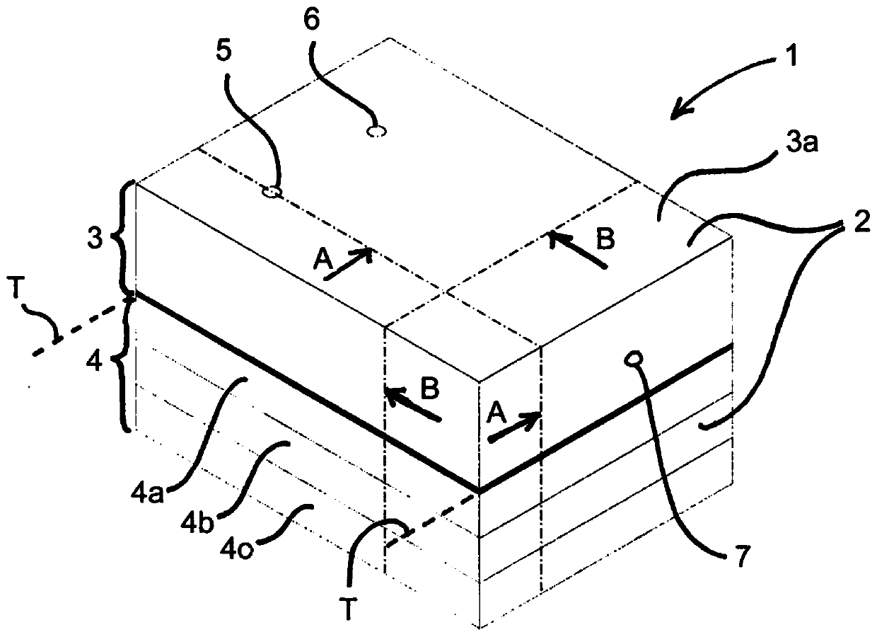
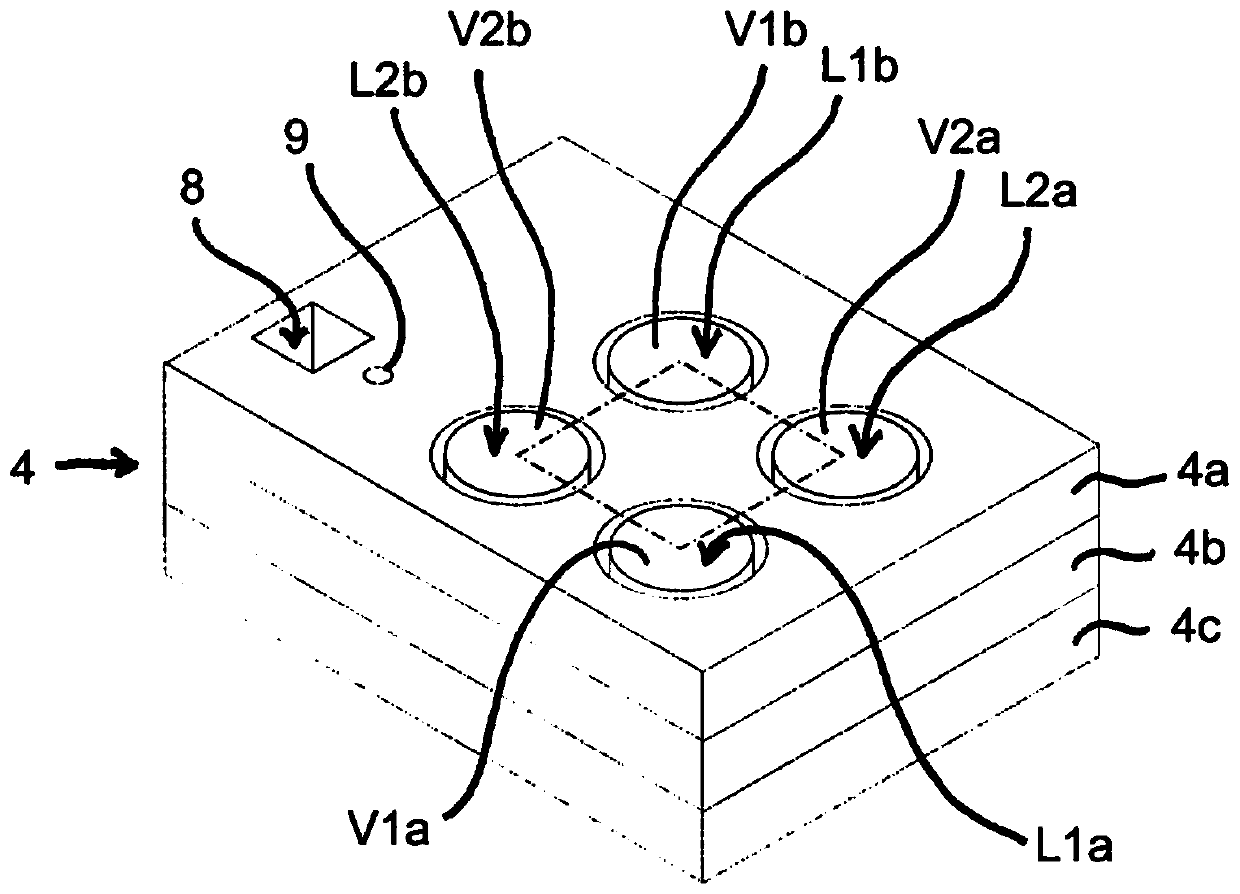
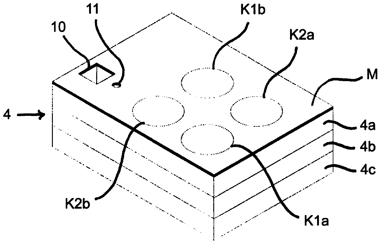
[0043] Figure 1-8 Various (partial) views and cutouts are shown of an exemplary embodiment of an electropneumatic valve group 1 according to the invention, which comprises a total of two pilot valves P1, P2 and four power valves L1a, L1b, L2a, L2b. In this case, the pilot valve P1 is used for actuating and switching the first pair of power valves L1a, L1b, and the pilot valve P2 is used for actuating and switching the second pair of power valves L2a, L2b, as will be explained further below.

[0044] in accordance with figure 1 Perspective view of housing 2 of an embodiment of valve bank 1 and according to Figure 7 and 8 (in accordance with figure 1 It can be seen from the sectional view of the section line A-A and B-B) of the valve group 1 that the casing 2 of the valve group 1 is composed of a pilot stage casing 3 and a power stage casing 4 in layers, wherein the pilot stage casing 3 The power stage housing 4 and the power stage housing 4 adjoin one another along a subs...


PUM


Abstract

An electropneumatic valve block comprises an electropneumatic pilot stage and a pneumatic power stage controlled by the pilot stage, the pilot stage having at least one pilot valve. Each pilot valve switches at least two power valves that are pneumatically coupled to the pilot valve. The valve block has a housing with an electrical signal inlet, a compressed air connection, a ventilation connection and a working outlet. The housing is formed in layers with at least one pilot stage housing and at least one power stage housing adjoining the pilot stage housing along a substantially planar separation plane. A sealing element is accommodated or formed between at least one pilot stage housing and at least one power stage housing, the sealing element enclosing a control pressure region arranged between the pilot stage housing and the power stage housing. The control pressure region has two control regions for the two power valves and a channel-like connection between the two control regions with a defined flow cross-sectional area. The outlet of the associated pilot valve, which is provided in the pilot stage housing, leads into the control pressure region.

Description

technical field [0001] The invention relates to an electropneumatic valve block, in particular for actuating a pneumatic operating element, comprising an electropneumatic pilot stage and a pneumatic power stage controlled by the pilot stage, said pilot stage having at least one pilot valve And the power stage has at least two power valves, wherein each pilot valve switches at least two power valves pneumatically coupled to the pilot valve, and wherein the valve block has a housing, the housing The body has an electrical signal inlet, a compressed air connection, at least one ventilation connection and at least one working outlet. Background technique [0002] Such electropneumatic valve blocks are known from the prior art in various designs and serve as state regulators (controlled by means of electronic control signals) for actuating a pneumatic working element to be adjacent to at least one working outlet (such as a pneumatic system or pneumatic drive). [0003] Since th...

Claims


Application Information

Patent Timeline
Patent Type & Authority Patents(China)
IPC IPC(8): F15B21/00F15B13/04
CPCF15B11/006F15B11/06F15B13/0405F15B13/0431F15B13/081F15B13/0828F15B2013/006F15B2211/30575F15B2211/8855F15B21/003F16K27/003F15B2211/71Y10T137/87209Y10T137/87201F16K31/423F15B11/076F15B13/0889
Inventor G.莫尔纳M.基恩B.希尔德布兰特S.内斯M.施罗本豪泽D.哈勒J.沙伊布勒M.比尔拉
Owner HOERBIGER FLOW CONTROL GMBH
Why Eureka
Try Eureka