
Cloth feeding mechanism of embroidery machine

A technology of a cloth feeding mechanism and an embroidery machine, which is applied in the field of embroidery machines, can solve problems such as reducing embroidery quality, achieve the effect of improving embroidery quality and ensuring flatness

Inactive Publication Date: 2017-04-19
江苏润源控股集团有限公司
View PDF8 Cites 2 Cited by
  • Summary
  • Abstract
  • Description
  • Claims
  • Application Information

AI Technical Summary

Problems solved by technology

[0003] The cloth feeding mechanism of this structure has the following defects in the work, that is, when the cloth between the front clamping roller group and the rear cloth clamping roller group is tightened for embroidery, the cloth will shrink inward along the left and right directions of the machine head. , thereby seriously reducing the embroidery quality

Method used


Image

  • Cloth feeding mechanism of embroidery machine
  • Cloth feeding mechanism of embroidery machine
  • Cloth feeding mechanism of embroidery machine

Examples


Embodiment Construction

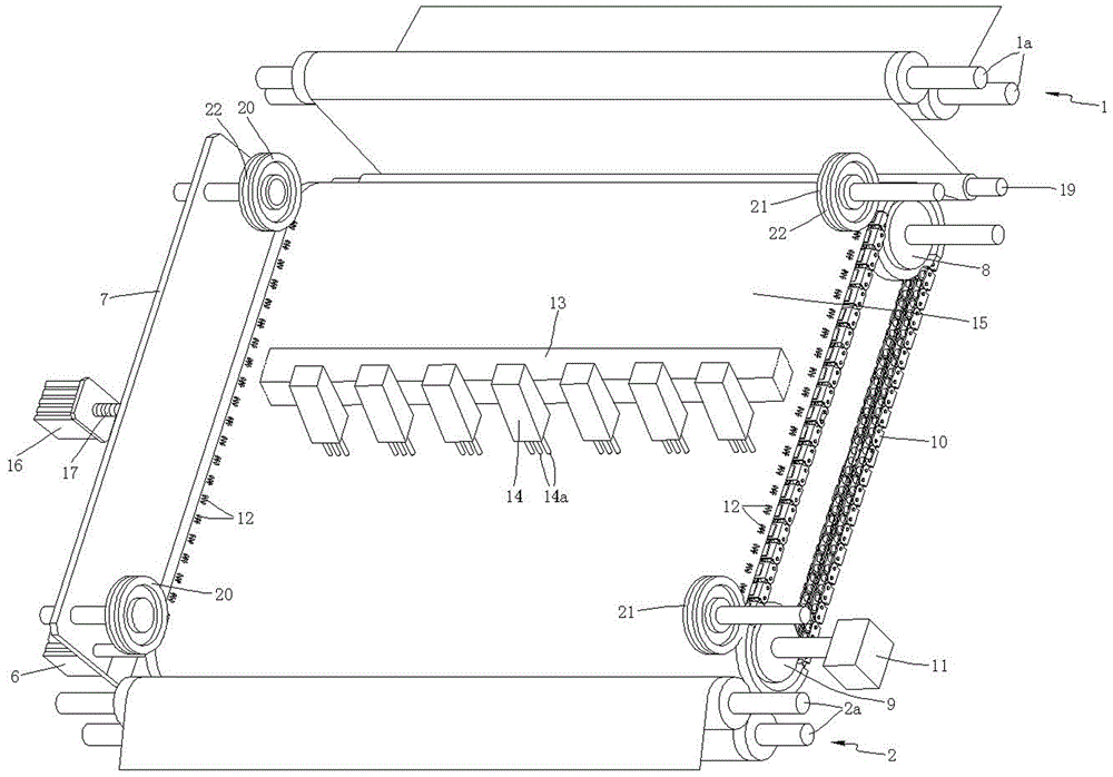
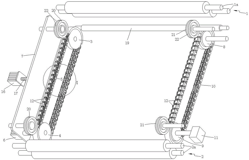
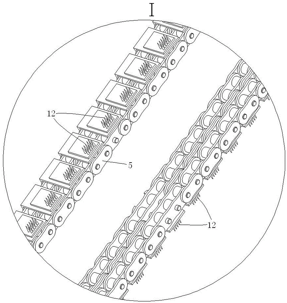
[0019] see Figure 1 to Figure 4 Shown is a cloth feeding mechanism of an embroidery machine, the embroidery machine includes a machine head 14 fixedly installed on the crossbeam 13 of the embroidery machine, and a plurality of embroidery needles 14a for embroidery are installed at the bottom of the machine head 14. The cloth feeding mechanism includes a front clamping roller set 1 and a rear clamping roller set 2 respectively arranged on the front and rear sides of the machine head 14. The front cloth clamping rollers 1a arranged in pairs, the rear cloth clamping roller group 2 includes the rear cloth clamping rollers 2a which are rotatably installed on the embroidery machine frame through bearings and arranged in pairs up and down, the embroidery machine frame is not shown in the figure . During work, the embroidery needle 14a on the machine head 14 embroiders the cloth 15 sent between the front clamping roller group 1 and the rear clamping roller group 2, and the cloth fee...


PUM


Abstract

The invention discloses a cloth feeding mechanism of an embroidery machine. The cloth feeding mechanism comprises a front cloth clamping roller set, a rear cloth clamping roller set, a left chain transmission mechanism and a right chain transmission mechanism, wherein the front cloth clamping roller set and the rear cloth clamping roller set are arranged in front of and at back of a machine head respectively; the left chain transmission mechanism and the right chain transmission mechanism are arranged on the left side and the right side of the machine head respectively; the left chain transmission mechanism comprises a first driven chain wheel, a first driving chain wheel and a first chain, the first driving chain wheel is driven by a first motor to rotate, the first motor is fixedly mounted on a vertical plate which is parallel with the first chain and spaced with the first chain by a certain distance, the first driven chain wheel is rotationally mounted on the vertical plate, and the vertical plate is driven by a linear drive device to move horizontally; the right chain transmission mechanism comprises a second driven chain wheel, a second driving chain wheel and a second chain, the second driving chain wheel is driven by a second motor to rotate, the second driven chain wheel is rotationally mounted on a rack of the embroidery machine, and a plurality of insertion needles are mounted on the outside of each chain link of the first chain and the second chain. The cloth feeding mechanism of the embroidery machine guarantees the flatness of cloth between the front cloth clamping roller set and the rear cloth clamping roller set, and the embroidery quality is improved.

Description

technical field [0001] The invention relates to an embroidery machine, in particular to a cloth feeding mechanism of the embroidery machine. Background technique [0002] There is a cloth feeding mechanism for an existing embroidery machine. The embroidery machine includes a machine head fixedly installed on the crossbeam of the embroidery machine. Several embroidery needles for embroidery are installed at the bottom of the machine head. The cloth feeding mechanism includes The front and rear cloth clamping roller sets on the front and rear sides of the machine head. The cloth roller set includes rear cloth rollers which are rotatably installed on the frame of the embroidery machine and arranged in pairs up and down. When working, the embroidery on the machine head is fed into the gap between the front cloth roller group and the rear cloth roller group. fabric for embroidery. [0003] The cloth feeding mechanism of this structure has the following defects in operation, tha...

Claims


Application Information

Patent Timeline
Patent Type & Authority Patents(China)
IPC IPC(8): B65H20/02B65H23/032
CPCB65H20/02B65H23/0324
Inventor 王占洪郭锐春马晓光
Owner 江苏润源控股集团有限公司
Learn More