Three-portal-frame material taking machine

A technology of reclaimer and tripod, applied in the direction of lifting device, etc., can solve the problems of increasing cost, increasing size, limited lifting height of reclaimer, etc., and achieve the effect of improving safety and lifting safety and stability

Active Publication Date: 2015-12-09
ZHEJIANG DINGLI MACHINERY CO LTD
View PDF6 Cites 1 Cited by
  • Summary
  • Abstract
  • Description
  • Claims
  • Application Information

AI Technical Summary

Problems solved by technology

[0004] The lifting height of the above-mentioned reclaimers is limited. To obtain a reclaimer that can be raised higher, it is usually oversized, which significantly increases the cost

Method used


Image

  • Three-portal-frame material taking machine
  • Three-portal-frame material taking machine
  • Three-portal-frame material taking machine

Examples


Embodiment 1

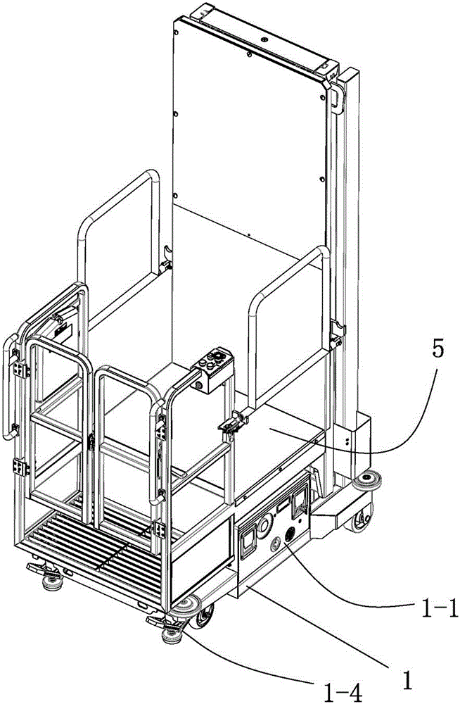
[0053] A three-door reclaimer has a chassis 1, a lifting structure and a reclaiming platform 5. The overall structure is as figure 1 As shown, there are wheels at the bottom of the chassis 1, which do not have the ability to actively rotate, so that the whole machine needs external force to move. Brake feet 1-4 are arranged next to the front wheel. When the brake feet 1-4 are stepped on, the brake feet 1-4 can be offset against the carrier surface of the reclaimer, so that the reclaimer has at least part of the gravity. It is assigned to brake top feet 1-4 to generate static friction to achieve positioning.

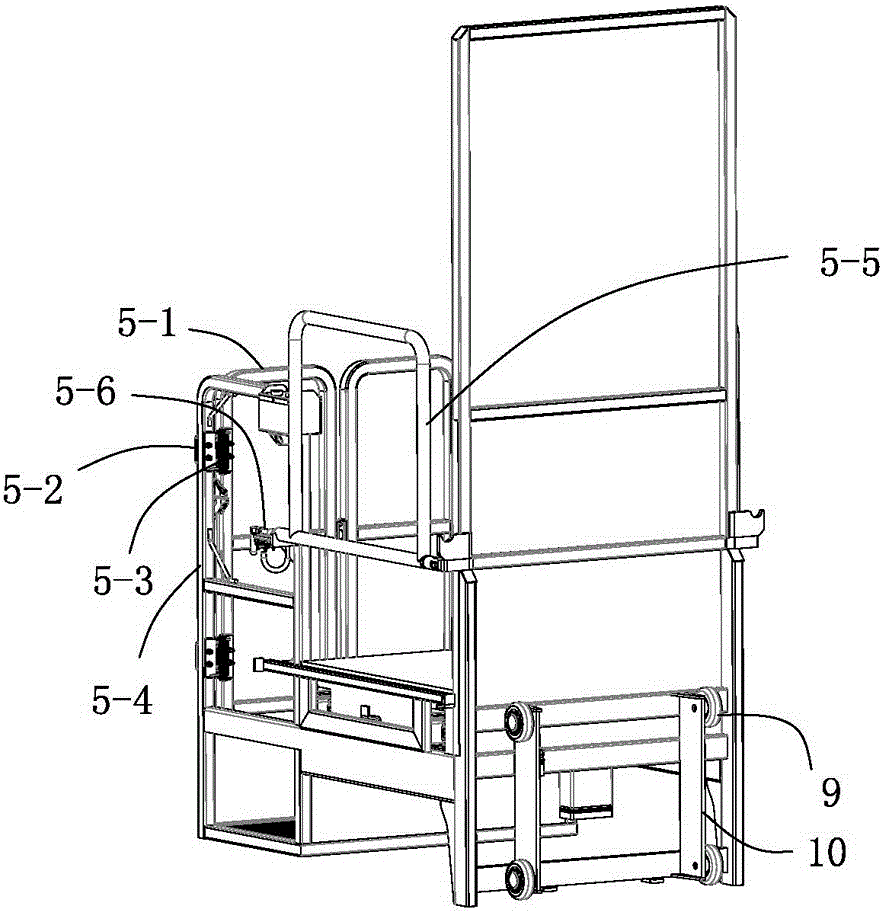
[0054] like figure 2 Shown is the structural diagram of the reclaiming platform 5 of the reclaimer. The material reclaiming platform 5 has a split double front door 5-1 and a scissor type side door 5-5, and the double front door 5-1 is installed on the material reclaiming platform through a limit block 5-2 and a torsion spring 5-3 5 on the frame 5-4, the front door 5...

Embodiment 2

[0064] A reclaimer, which has a chassis 1, a lifting structure and a reclaiming platform 5. The overall structure is as Figure 11 As shown, it is basically the same as Embodiment 1, the difference is that it is self-driven, such as Figure 4 As shown, it is driven by two rear active directional wheels 1-3, and is driven non-coaxially, each driven by an independent motor. Therefore, the forward, backward and turning directions of the reclaimer are all determined by the rotational direction and / or rotational speed difference of the two rear active orientation wheels 1-3. For example, when the direction of rotation and the rotational speed difference of the two rear active orientation wheels 1-3 are consistent, the reclaimer moves forward in a straight line or retreats in a straight line; if they all rotate forward, the rotation speed of the left wheel is greater than that of the right wheel. Then the reclaimer turns right while advancing.

[0065] The difference is also that...


PUM


Abstract

The invention relates to a three-portal-frame material taking machine and belongs to the technical field of manned lifting equipment. The three-portal-frame material taking machine comprises a chassis, a hydraulic lifting assembly, a chain wheel lifting assembly and a material taking platform. The hydraulic lifting assembly comprises a fixed portal frame, a hydraulic cylinder and a movable portal frame. The chain wheel lifting assembly comprises a chain wheel and a chain. The fixed portal frame is erected on the chassis and fixed to the chassis, and an ejector rod of the hydraulic cylinder is connected to the movable portal frame so as to drive the movable portal frame. One end of the chain is connected to the movable portal frame, and the other end of the chain is connected to a second movable portal frame. The second movable portal frame is lifted up and down by the aid of lifting movement of the movable portal frame and with the help of the chain wheel and the chain. The material taking platform is lifted up and down by the aid of lifting movement of the second movable portal frame and with the help of a second chain wheel and a second chain. The material taking machine is of a three-portal-frame structure and can be lifted higher under the condition that the size of the complete machine is not changed; moreover, the material taking machine has the advantage of being lifted safely and stably.

Description

technical field [0001] The invention relates to a three-gantry reclaimer, which belongs to the technical field of lifting equipment, in particular to the technical field of manned lifting equipment. Background technique [0002] There are many ways to remove high-altitude objects. Among them, the method of shortening the distance between people and objects so that people can directly reach objects is the safest and most convenient. The reclaimer is designed based on this idea. However, the structure of the reclaimer is various, and different structures determine its different applicable occasions. Take the display shelf of a large supermarket as an example. The shelf is more than 2 meters high. Tools are needed to remove items from the high shelf. The general-purpose scissor lift platform has potential safety hazards. The portal reclaimer can solve this problem. Therefore, The gantry reclaimer has a good application prospect in supermarkets, warehouses and other occasions...

Claims


Application Information

Patent Timeline
IPC IPC(8): B66F11/04
Inventor 许树根
Owner ZHEJIANG DINGLI MACHINERY CO LTD
Why Eureka
Try Eureka