Base plate cutting machine and base plate long edge cutting and splitting method

A cutting machine and cutting mechanism technology, applied in glass cutting devices, glass manufacturing equipment, glass production, etc., can solve the problems of increased takt time and reduced production efficiency, and achieve the goal of reducing takt time, improving production efficiency, and reducing waiting time Effect

Active Publication Date: 2015-12-09
SHENZHEN CHINA STAR OPTOELECTRONICS TECH CO LTD
View PDF4 Cites 7 Cited by
  • Summary
  • Abstract
  • Description
  • Claims
  • Application Information

AI Technical Summary

Problems solved by technology

At present, when the substrate machine produces substrate long-side cutting products, such as figure 2 As shown, the substrate carrying platform (including platform 11, platform 12, platform 13, and platform 14) needs to move from the dotted line position in the figure to the solid line position to realize the substrate loading, that is, platform 11 and platform 14 need to move from the outside to the inside Displacement S, at the same time, the cutting mechanism and the split mechanism symmetrically located on both sides of the substrate carrying platform also need to move laterally to the inside to meet the cutting split action. When the split action is completed, the platform 11 (platform 14), the cutting mechanism and the split mechanism need to move outward Move horizontally to the position where the short side is cut (the position of the dotted line), and then the split mechanism moves laterally to the outside alone, and walks to the top of the residual material funnel to carry out the process of cleaning the residual material. Only relying on the outward movement of the split mechanism cannot meet its requirements. Stroke; when the platform 11 moves laterally to the short side cutting position, the upstream substrate cannot be moved into the substrate carrying platform, and the substrate that has been cut cannot be carried out. Productivity

Method used


Image

  • Base plate cutting machine and base plate long edge cutting and splitting method
  • Base plate cutting machine and base plate long edge cutting and splitting method
  • Base plate cutting machine and base plate long edge cutting and splitting method

Examples


Embodiment Construction

[0036] The following will clearly and completely describe the technical solutions in the embodiments of the present invention with reference to the drawings in the embodiments of the present invention.

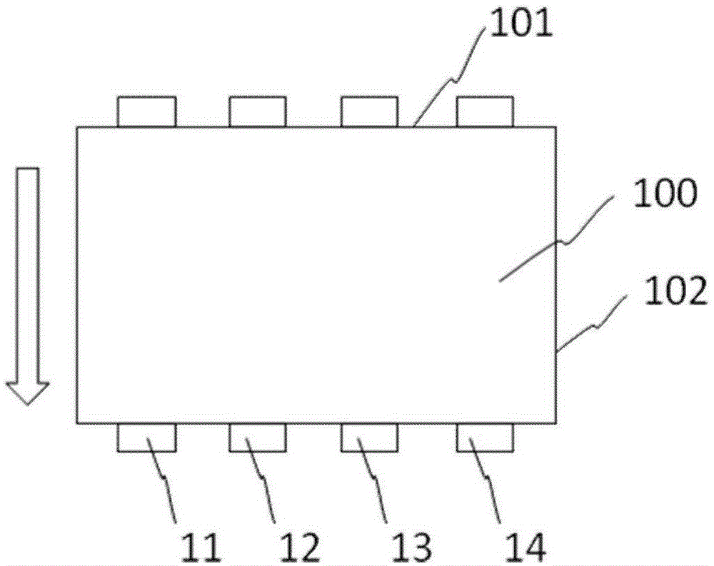
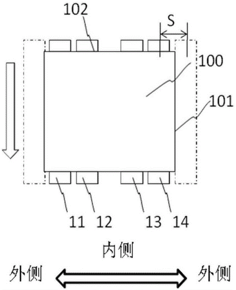
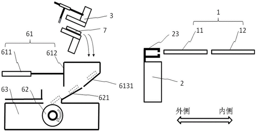
[0037] Embodiment 1 of the present invention provides a substrate cutting machine, such as Figure 3-5 , mainly including: a substrate carrying platform 1, which is divided into four pieces, namely a platform 11, a platform 12, a platform 13 and a platform 14, wherein the platform 11 is symmetrical to the platform 14, and the platform 12 is symmetrical to the platform 13, and its function is to carry the glass substrate; The cutting mechanism 2 includes a cutter wheel mechanism, which is used to cut and mark the substrate to facilitate the subsequent splitting process, and a substrate clip mechanism 23 located above the cutter wheel mechanism, whose function is to carry the substrate; the split mechanism 3, whose function is to carry out The lobes separate CF residual material...


PUM


Abstract

The present invention discloses a base plate cutting machine, which comprises a base plate bearing platform, a cutting mechanism, a splitting mechanism, a residue material collection mechanism and a base plate conveying mechanism, wherein the outer side of the base plate bearing platform is sequentially provided with the cutting mechanism and the splitting mechanism, the residue material collection mechanism is positioned below the splitting mechanism, the cutting mechanism comprises a cutter wheel mechanism and a base plate clamp mechanism, the residue material collection mechanism comprises a residue material collection funnel, a residue material mincing mechanism and a residue collection box, the residue material collection funnel, the residue material mincing mechanism and the residue collection box are sequentially communicated from top to bottom, the residue material collection funnel comprises a funnel drive device and a funnel main body, the funnel drive device drives the funnel main body to move, and the movement path covers the movement path of the splitting mechanism. The present invention further provides a base plate long edge cutting and splitting method. With the base plate cutting machine and the base plate long edge cutting and splitting method of the present invention, the waiting time for the movement of the splitting mechanism onto the residue material collection funnel to clean the residue material before the loading and the unloading of the base plate and the time of the moving back and forth can be avoided, the takt time of the base plate cutting and splitting is reduced, and the production efficiency is improved.

Description

technical field [0001] The invention relates to the field of substrate cutting, in particular to a substrate cutting machine and a method for cutting and slitting a substrate on a long side. Background technique [0002] The purpose of the substrate cutting machine is to cut off the dummy at the edge of the CF surface, that is, the residual material, to expose the HVACuringPad on the TFT surface, so that subsequent processes including UV1, AOI, and MAC can be powered on and used for the HVACuringPad. According to the position of the HVACuringPad, there are two types: long-side cutting and short-side cutting. Take G8.5Glass as an example, the size of the Glass is 2200mm*2500mm, and the HVACuringPad is designed at 2200mm. The cutting method of the two opposite sides is called the short side Cutting, HVACuringPad is designed to cut two opposite sides of 2500mm, we call it long side cutting, such as Figure 1-2 , the glass substrates 100, 101 are the long sides of the glass subs...

Claims


Application Information

Patent Timeline
Patent Type & Authority Applications(China)
IPC IPC(8): C03B33/02
CPCY02P40/57
Inventor 刘小成
Owner SHENZHEN CHINA STAR OPTOELECTRONICS TECH CO LTD
Why Eureka
Try Eureka