Scutcher

A technology of cotton cleaning machine and frame, applied in the field of cotton cleaning machine, can solve the problems of low impurity content of seed cotton, uneven distribution of work rolls, and difficulty in achieving the best cleaning effect, so as to achieve good cleaning effect and improve cleaning. effect of effect

Active Publication Date: 2015-12-09
胡玉白
View PDF8 Cites 2 Cited by
  • Summary
  • Abstract
  • Description
  • Claims
  • Application Information

AI Technical Summary

Problems solved by technology

In the past, cotton was mainly picked by hand. When picking, the quality of cotton was high, and the impurity rate of seed cotton was low, and the impurities were mainly cotton leaves, dust and other fine impurities. Cotton accounts for an increasing proportion of seed cotton, and machine-picked cotton inevitably contains a large amount of impurities, which include not only fine impurities such as cotton leaves and dust, but also large impurities such as cotton stalks, cotton boll shells, and ropes. All are fibrous, entangled with cotton fibers and difficult to separate
Although the existing cleaning machine has a certain cleaning effect, it has the following disadvantages: one, the existing cleaning machine utilizes the blowing effect of the blower fan, and the positive pressure of the two-phase flow of seed cotton and air enters the cotton cleaning machine, and the seed cotton Under the blowing of the positive air flow, it cannot be evenly distributed on the work rolls, so it is difficult to achieve the best cleaning effect; 2. After cleaning, the seed cotton needs to be sent to the cotton storage box by an additional fan

Method used


Image

  • Scutcher

Examples


Embodiment Construction

[0025] In order to clearly illustrate the technical features of this solution, the present invention will be described in detail below through specific implementation modes and in conjunction with the accompanying drawings.

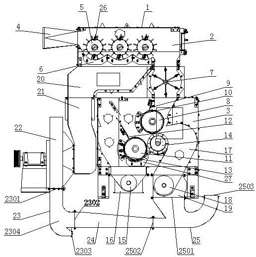
[0026] As shown in the figure, the present invention comprises frame and casing 1, is provided with upper chamber 2 and lower chamber 3 in casing 1, is provided with and communicates with upper chamber 2 on one side of casing 1 top. The feeding port 4 is provided with three nailing rollers 5 arranged side by side on the frame near the feeding port 4 in the upper chamber 2, and three nailing rollers 5 corresponding to the nailing rollers 5 are arranged below the nailing rollers 5. 1. Interconnected separation net bottoms 6, the separation net bottoms 6 have leakage holes, and the upper surface of each separation net bottom 6 is an arc surface matched with the scraper 26 of the spike roller 5. Each nailing roller 5 is provided with a scraper 26 matched with...


PUM


Abstract

The invention relates to a scutcher, wherein a group of barbed nail rollers distributed in parallel are arranged on a rack, close to a material feed hole, in an upper chamber, a separating net bottom is arranged below the barbed nail rollers, the upper chamber is communicated with a lower chamber through an airlock valve, an upper rack roller, a lower rack roller, a cotton brushing roller, an impurity discharge auger, a cotton discharge passage and a cotton discharge auger are arranged in the lower chamber, a negative pressure chamber is arranged in an enclosure on the other side of the lower part of the upper chamber, the upper chamber is communicated with the upper end of the negative pressure chamber through the separating net bottom, the lower end of the negative pressure chamber is connected with an air suction end of a fan through an air suction bellow, the inlet of a three-way elbow is connected with an air blow end of the fan, an upper outlet of the three-way elbow is connected with one end of a flat air pipe, the other end of the flat air pipe is communicated with a lower inlet of a cotton blow pipe, and a cotton discharge hole is communicated with an upper inlet of the cotton blow pipe. The scutcher is reasonable in structural design, convenient to use, and good in cotton cleaning effect, and the unginned cotton after scotching can be fed into a cotton storage box without an additionally arranged fan.

Description

technical field [0001] The invention relates to a cleaning machine. Background technique [0002] Before cotton processing, the impurities in the seed cotton must be cleaned first, and the cotton cleaning machine is a device used to remove impurities in the seed cotton. In the past, cotton was mainly picked by hand. When picking, the quality of cotton was high, and the impurity rate of seed cotton was low, and the impurities were mainly cotton leaves, dust and other fine impurities. Cotton accounts for an increasing proportion of seed cotton, and machine-picked cotton inevitably contains a large amount of impurities, which include not only fine impurities such as cotton leaves and dust, but also large impurities such as cotton stalks, cotton boll shells, and ropes. They are all fibrous, entangled with cotton fibers and difficult to separate. Although the existing cleaning machine has a certain cleaning effect, it has the following disadvantages: one, the existing cleaning ...

Claims


Application Information

Patent Timeline
IPC IPC(8): D01G9/06D01G9/08
Inventor 胡玉白
Owner 胡玉白
Why Eureka
Try Eureka