High-speed train wheel-mounted brake disc with slider structure and installation method

A technology for high-speed trains and brake discs, applied in the direction of brake discs, brake types, brake components, etc., can solve problems such as unfavorable wheel strength, reduce the risk of fatigue cracks, reduce the amount of processing, and improve production efficiency Effect

Active Publication Date: 2017-07-11
CRRC QINGDAO SIFANG ROLLING STOCK RES INST
View PDF9 Cites 0 Cited by
  • Summary
  • Abstract
  • Description
  • Claims
  • Application Information

AI Technical Summary

Problems solved by technology

[0003] Since the wheel needs to be installed with 6 positioning pins and 12 bolt holes, it is necessary to process 18 through holes in the circumferential direction of the wheel, which is very unfavorable to the strength of the wheel

Method used


Image

  • High-speed train wheel-mounted brake disc with slider structure and installation method
  • High-speed train wheel-mounted brake disc with slider structure and installation method
  • High-speed train wheel-mounted brake disc with slider structure and installation method

Examples


Embodiment 1

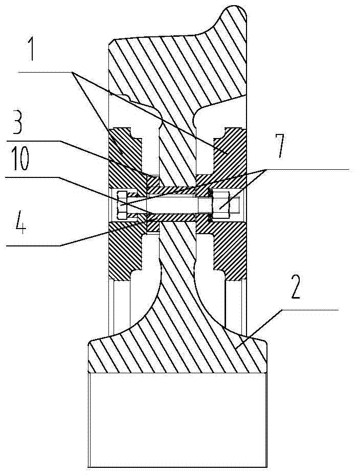
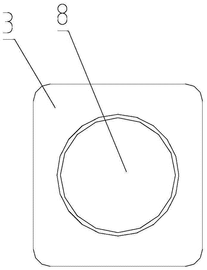
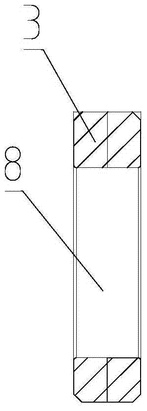
[0028] A high-speed train wheel-mounted brake disc with a slider structure, including two disc bodies 1, a wheel 2, fasteners, and a slider 3 and a sleeve 4; disc body through holes are evenly distributed along the circumference of the disc body 1; The disc body through holes include disc body bolt holes 5 and chute holes 11 arranged at intervals; wheel through holes are evenly distributed along the wheel circumference; wheel through holes include sleeve holes and wheel bolt holes arranged at intervals; the number of wheel through holes and The number of through holes in the disc body is the same. In this embodiment, there are 12 disc through holes and 12 wheel through holes, and the disc through holes on each disc include 9 disc bolt holes 5 and 3 chute holes 11; A chute 6, an angle of 30° is spaced between adjacent chute holes 11 and disc body bolt holes 5, and an angle of 120° is spaced between two adjacent chute 6s; similarly, adjacent sleeve holes and The interval betwee...

Embodiment 2

[0039] Unlike Embodiment 1, this embodiment provides a structure without wheel bolt holes.

[0040] There are 8 disc through holes and 8 wheel through holes. The disc through holes on each disc include 4 disc bolt holes and 4 chute holes 11; there are 4 chute 6 on each disc, and the wheel The through hole includes 8 sleeve holes, the interval between the adjacent chute holes 6 and the plate bolt holes 5 is 45°, and the interval between two adjacent chute 6 is 90°; similarly, the adjacent The interval between the sleeve holes is 45°, and the interval between two adjacent slide block holes 8 is 45°; therefore, when the wheel-mounted brake shaft is assembled, 8 slide blocks and 8 sleeves are needed.

[0041] The installation method of the high-speed train wheel brake disc, the steps are as follows:

[0042] S1: Take 4 sleeves 4, and insert the 4 sleeves 4 into the sleeve holes of the wheel 2 at intervals of 90°,

[0043] S2: Take 4 sliders 3 and insert them on the sleeve 4;

...


PUM


Abstract

A high-speed train wheel-mounted brake disc with a slider structure, including two disc bodies and wheels, as well as sliders and sleeves; disc through holes are evenly distributed along the circumference of the disc body; The grooves do not penetrate the disc surface on both sides; the disc body through holes include disc body bolt holes and chute arranged at intervals; wheel through holes are evenly distributed along the wheel circumference; the wheel through holes include sleeve holes and wheel bolts arranged at intervals hole; the number of wheel through holes is the same as the number of disc through holes, and the number is less than 18; the slider can be inserted into the chute, and the two have a clearance fit; the sleeve can be inserted into the gap between the sleeve and the sleeve hole in the slider hole Cooperate. The invention adopts the structure of the slider and the sleeve to replace the mechanism of the positioning pin in the original wheel-mounted brake disc, which reduces the number of processing holes on the wheel and the wheel disc, reduces the risk of fatigue cracks at the wheel through-hole, and improves The service life of the wheel.

Description

technical field [0001] The invention belongs to the technical field of train braking devices, and designs a brake disc structure, in particular to a high-speed train wheel-mounted brake disc with a slider structure and an installation method thereof. Background technique [0002] At present, the basic brakes of domestic CRH series EMUs all adopt disc brakes, while EMUs are basically equipped with wheel-mounted brake discs. The current CRH series EMU wheel-mounted brake disc is mainly composed of 2 disc bodies, 6 positioning pins and 12 sets of fasteners; the disc body is a ring with a heat dissipation rib structure and there are 6 etc. Circumferentially distributed chute, in addition, there are 12 equicircumferentially distributed bolt holes on the disc body; the positioning pin is a solid shaft, and the cylindrical surface at both ends of the cylindrical shaft is milled to a certain depth symmetrically in the axial direction. After milling, the two The plane and the center...

Claims


Application Information

Patent Timeline
Patent Type & Authority Patents(China)
IPC IPC(8): F16D65/12F16D65/095
Inventor 王飞鲁文超于钦顺张昕张志强
Owner CRRC QINGDAO SIFANG ROLLING STOCK RES INST
Why Eureka
Try Eureka