
Bearing lubricating system for disc separator

A disc separator and bearing lubrication technology, which is applied to the lubrication of engines, centrifuges, mechanical equipment, etc., can solve the problems of long distance between upper and lower bearings of multiple bearings, insufficient lubrication, etc., and achieve low production cost, rigorous structure, and layout reasonable effect

Active Publication Date: 2015-12-09
CSSC NANJING LUZHOU MACHINE
View PDF6 Cites 1 Cited by
  • Summary
  • Abstract
  • Description
  • Claims
  • Application Information

AI Technical Summary

Problems solved by technology

[0003] The technical problem to be solved by the present invention is to overcome these technical defects and provide a bearing lubrication system for disc-type disc separators, which can effectively solve the problem of insufficient lubrication caused by multiple bearings connected in series or a long distance between the upper and lower bearings, and ensure the lubrication of the bearings. reliability

Method used


Image

  • Bearing lubricating system for disc separator
  • Bearing lubricating system for disc separator
  • Bearing lubricating system for disc separator

Examples


Embodiment

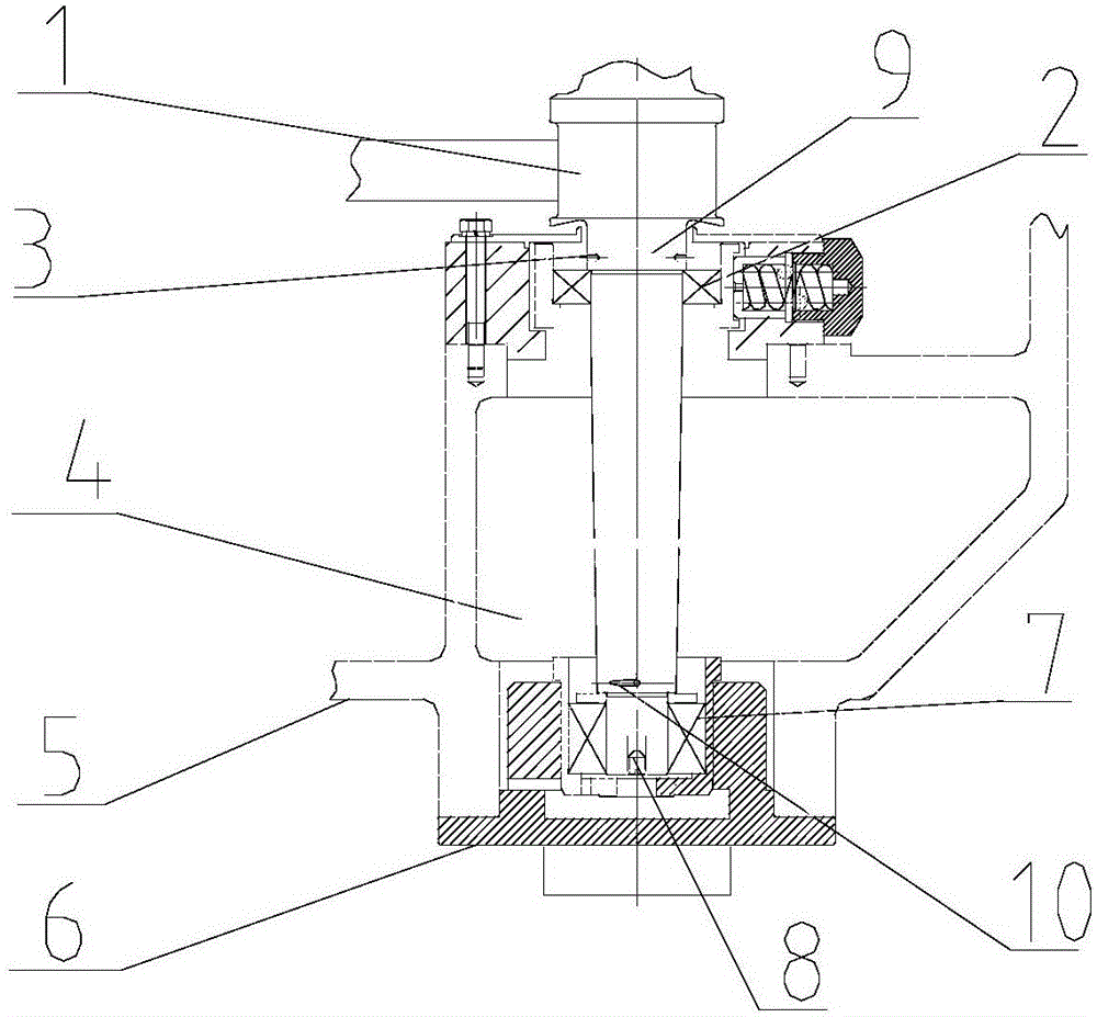
[0017] The invention provides a disc separator bearing lubrication system, such as figure 1 Shown: comprise machine base 5, and the vertical shaft system and base 6 that are fixed on the machine base. The vertical shaft system includes a vertical shaft 1, an upper bearing 2 and a lower bearing 7, and a machine base cavity 4 is also provided on the machine base.

[0018] The vertical shaft passes through the oil chamber of the machine base, its upper end is connected with the upper end of the machine base through the upper bearing, and the lower end is connected with the lower end of the machine base through the lower bearing; the vertical shaft is provided with a central oil hole in the axial direction, and the central oil hole is circular. The hole diameter is 10 mm. At the same time, the upper end of the central oil hole is a closed end, and the lower end is fixed and closed by bolts 8 .

[0019] Side oil holes are arranged radially on the vertical shaft close to the upper...


PUM


Abstract

The invention discloses a bearing lubricating system for a disc separator. The bearing lubricating system comprises a machine base, a vertical shaft system fixed to the machine base and a foundation. The vertical shaft system comprises a vertical shaft, an upper bearing and a lower bearing. The machine base is provided with a machine base cavity. The vertical shaft penetrates a cavity body of an oil cavity of the machine base. The upper end of the vertical shaft is connected with the upper end of the machine base through the upper bearing. The lower end of the vertical shaft is connected with the lower end of the machine base through the lower bearing. The vertical shaft is provided with a center oil hole in the axial direction. The portions, close to the upper bearing and the lower bearing, of the vertical shaft are provided with side oil holes in the radial direction. A lower bearing lubricating oil way is formed by a gap among the oil cavity of the machine base, the lower bearing, the machine base and the foundation. An upper bearing lubricating oil way is formed by a vertical stand center hole, the side oil holes, the upper bearing and the oil cavity of the machine base. The bearing lubricating system can control the amount of lubricating oil at the bottom bearing and can adjust the amount of lubricating oil at the top bearing, so that the problem that lubricating is insufficient due to the fact that multiple bearings are connected in series or the distance between an upper bearing and a lower bearing is longer is solved effectively, and the reliability of gears and the bearings is guaranteed.

Description

technical field [0001] The invention relates to a bearing lubricating system, in particular to a bearing lubricating system for a disc separator, which belongs to the technical field of engineering machinery. Background technique [0002] The drive system of the disc separator is mainly divided into gear drive, belt drive and direct drive. The bearing lubrication of the gear transmission system mainly relies on part of the gears being immersed in lubricating oil, and the oil is brought out to lubricate the bearings when rotating; the direct drive has no bearings, and there is no bearing lubrication problem. The belt drive mainly relies on the oil pump installed on the bearing to suck the lubricating oil to lubricate the upper and lower bearings. Due to the larger gears in the gear transmission lubrication system, the oil chamber is also larger, the oil chamber is more complicated, and the oil temperature rise is also higher. The belt transmission system is mainly lubricate...

Claims


Application Information

Patent Timeline
Patent Type & Authority Applications(China)
IPC IPC(8): F16N7/36B04B15/00
Inventor 郑加洲季梅莲肖海赵奇峰王友强季云芳李邦李丽王芳
Owner CSSC NANJING LUZHOU MACHINE
Learn More