
Oil-cooled motor bearing lubricating structure

A technology of motor bearing and lubricating structure, applied in the direction of engine lubrication, shaft and bearing, bearing components, etc., can solve problems such as insufficient bearing lubrication, achieve stable and reliable lubrication, solve insufficient bearing lubrication, and improve feasibility.

Active Publication Date: 2021-04-16
ZHEJIANG LEAPMOTOR TECH CO LTD
View PDF8 Cites 0 Cited by
  • Summary
  • Abstract
  • Description
  • Claims
  • Application Information

AI Technical Summary

Problems solved by technology

The present invention utilizes the effect of high-speed centrifugal action on oil injection, and adopts the radial opening + bearing shoulder matching method, which can not only solve the problem of insufficient lubrication of the bearing, but also not be affected by the change of the rotational speed

Method used


Image

  • Oil-cooled motor bearing lubricating structure
  • Oil-cooled motor bearing lubricating structure
  • Oil-cooled motor bearing lubricating structure

Examples


Embodiment 1

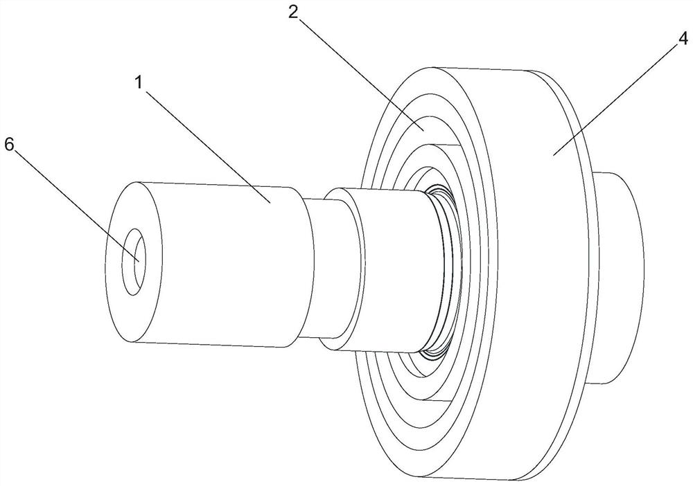
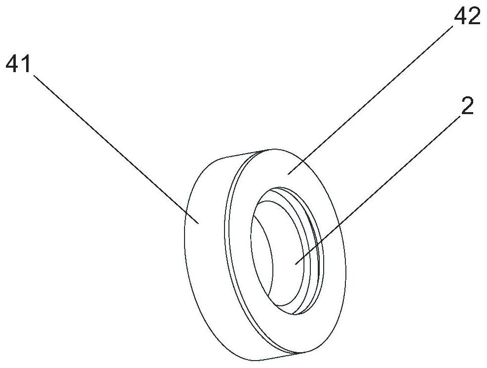
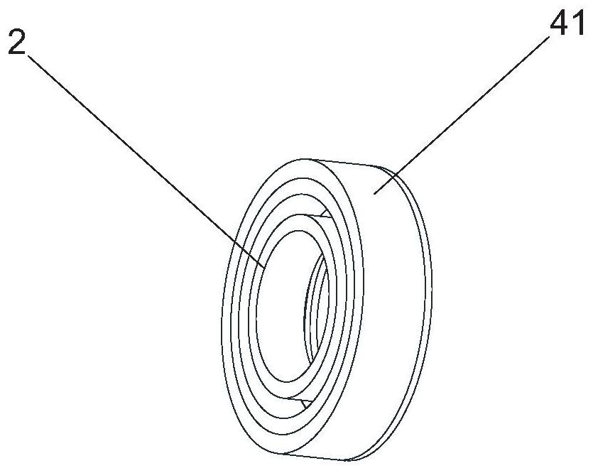
[0024] Such as Figure 1 to Figure 6 As shown, an oil-cooled motor bearing lubrication structure includes a rotor shaft 1 and a bearing 2, the bearing 2 is sleeved on the rotor shaft 1 and installed on the housing of the oil-cooled motor, and the rotor shaft 1 is provided with radial The oil supply channel 3 and the oil outlet port 5 of the radial oil supply channel 3 are located at the junction of the bearing 2 and the rotor shaft 1, and the bearing seat hole is provided with a bearing shoulder 4 that can prevent the oil from being thrown out centrifugally. The bearing retaining shoulder 4 includes an outer ring wall 41, an end face retaining ring 42 and a bearing supporting retaining ring 43, the outer ring wall 41 is located on the housing of the oil-cooled motor, and the end face retaining ring 42 is connected to the inner end surface of the outer ring wall 41, The bearing support retaining ring 43 is located at the junction of the outer ring wall 41 and the end face retai...

Embodiment 2

[0027] The outer ring wall 41 and the end face retaining ring 42 are integrally formed, and the bearing support retaining ring 43 is installed at the junction of the outer ring wall 41 and the end face retaining ring 42 . The inner peripheral surface of the outer ring of the bearing 2 is slightly higher than the bottom edge of the outer end surface of the bearing support retaining ring 43 . The included angle between the inclined plane and the axis of the bearing 2 is 28°. All the other are with embodiment 1.

Embodiment 3

[0029] The included angle between the inclined plane and the axis of the bearing 2 is 32°. All the other are with embodiment 1.


PUM


Abstract

The invention discloses an oil-cooled motor bearing lubricating structure which comprises a rotor shaft and a bearing. The bearing sleeves the rotor shaft and is installed on a shell of an oil-cooled motor. The rotor shaft is provided with a radial oil supply channel, and an oil outlet port of the radial oil supply channel is located at the joint of the bearing and the rotor shaft. A bearing retaining shoulder capable of preventing oil from being centrifugally thrown outwards is arranged in a bearing seat hole. According to the oil-cooled motor bearing lubricating structure, by utilizing the influence of the high-speed centrifugal effect on oil injection and adopting the radial hole and bearing retaining shoulder cooperation mode, the problem of insufficient bearing lubrication can be solved, and the influence of rotating speed changes is avoided. The oil way design can be effectively simplified, and the mass production implementation feasibility is improved.

Description

technical field [0001] The present invention relates to a bearing structure, more specifically, it relates to a bearing lubricating structure of an oil-cooled motor. Background technique [0002] In the prior art, in order to lubricate the bearings of oil-cooled motors, oil holes are usually opened axially on the surface of the rotor shaft. The lubricating effect of this lubricating structure is limited by the rotational speed of the rotor. , the axial oil can be sprayed smoothly into the bearing raceway to complete the bearing lubrication, but when the rotor speed is high, due to the large centrifugal force, the axial oil will float away in the radial direction and cannot approach the bearing, resulting in high-speed bearing lubrication Insufficient, there is a risk of bearing overheating, which seriously affects the service life of the bearing, and there is a large safety hazard during the operation of the bearing. The utility model patent with the publication number CN20...

Claims


Application Information

Patent Timeline
Patent Type & Authority Applications(China)
IPC IPC(8): F16N7/36F16N21/04F16N21/02F16C35/06H02K5/173
Inventor 吴元强
Owner ZHEJIANG LEAPMOTOR TECH CO LTD
Learn More