A direct incident optical arm magnifying 3D scanning probe

A three-dimensional scanning and probe technology, applied in the field of precision measurement, can solve the problems of high cost, low precision, and complex structure of the scanning probe, and achieve the effect of simplifying the structure, improving the measurement accuracy, and being easy to manufacture in batches.

Active Publication Date: 2019-06-07
山东信开源科技创新发展有限责任公司 +1
View PDF8 Cites 0 Cited by
  • Summary
  • Abstract
  • Description
  • Claims
  • Application Information

AI Technical Summary

Problems solved by technology

[0005] The purpose of the present invention is to overcome the above disadvantages of low precision of mechanical probe and trigger probe in the prior art, as well as the above-mentioned shortcomings of complex structure and high cost of scanning probe, and provide a simple structure and high measurement accuracy. Gao’s new three-dimensional scanning probe, which can measure the displacement of the probe in three directions, through displacement superposition, can compensate the position measurement deviation of the measured workpiece caused by the displacement of the measuring ball when it touches the measured workpiece, and obtain the measured More accurate measurement coordinates of the workpiece

Method used


Image

  • A direct incident optical arm magnifying 3D scanning probe
  • A direct incident optical arm magnifying 3D scanning probe
  • A direct incident optical arm magnifying 3D scanning probe

Examples


Embodiment 1

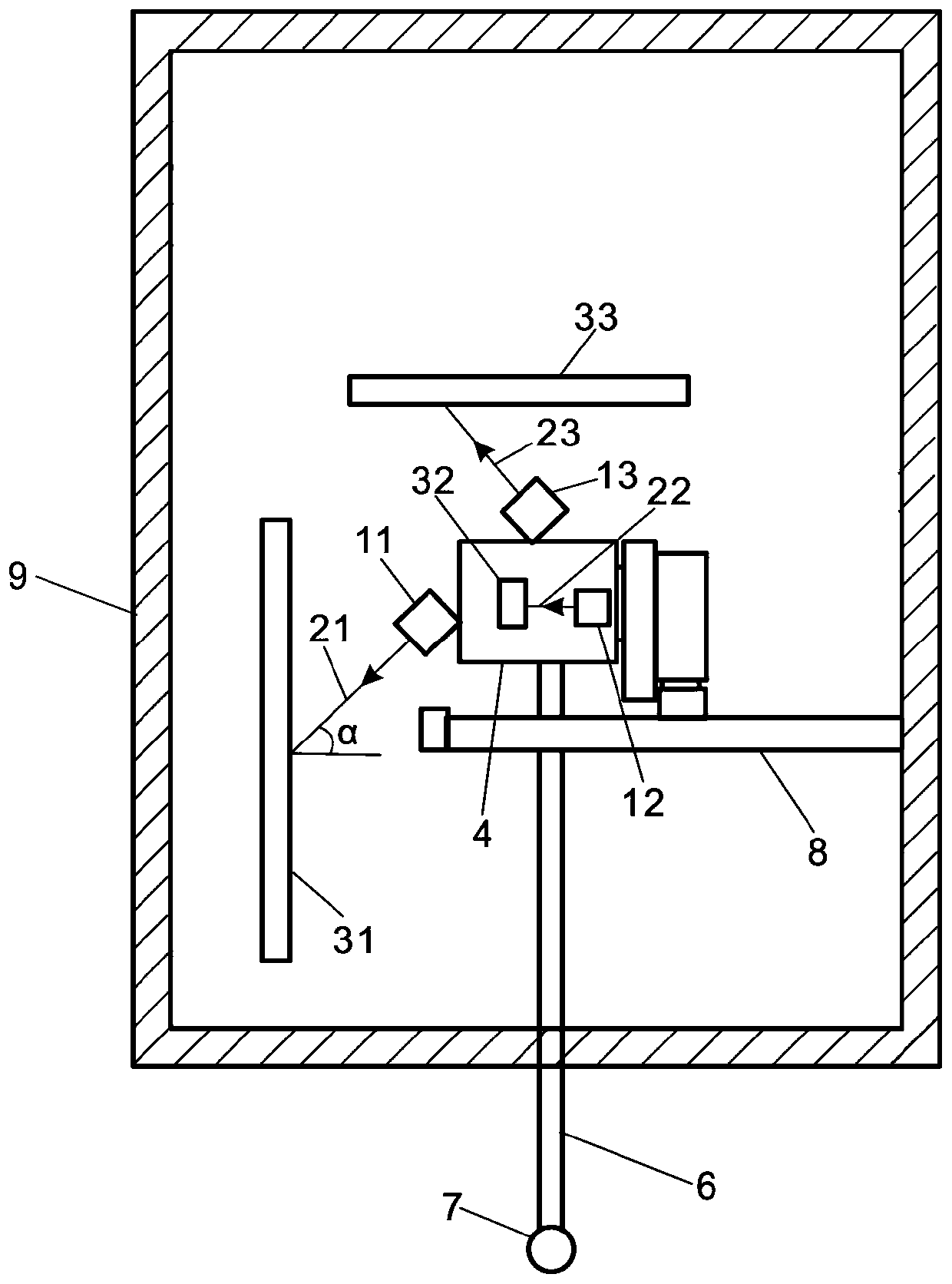
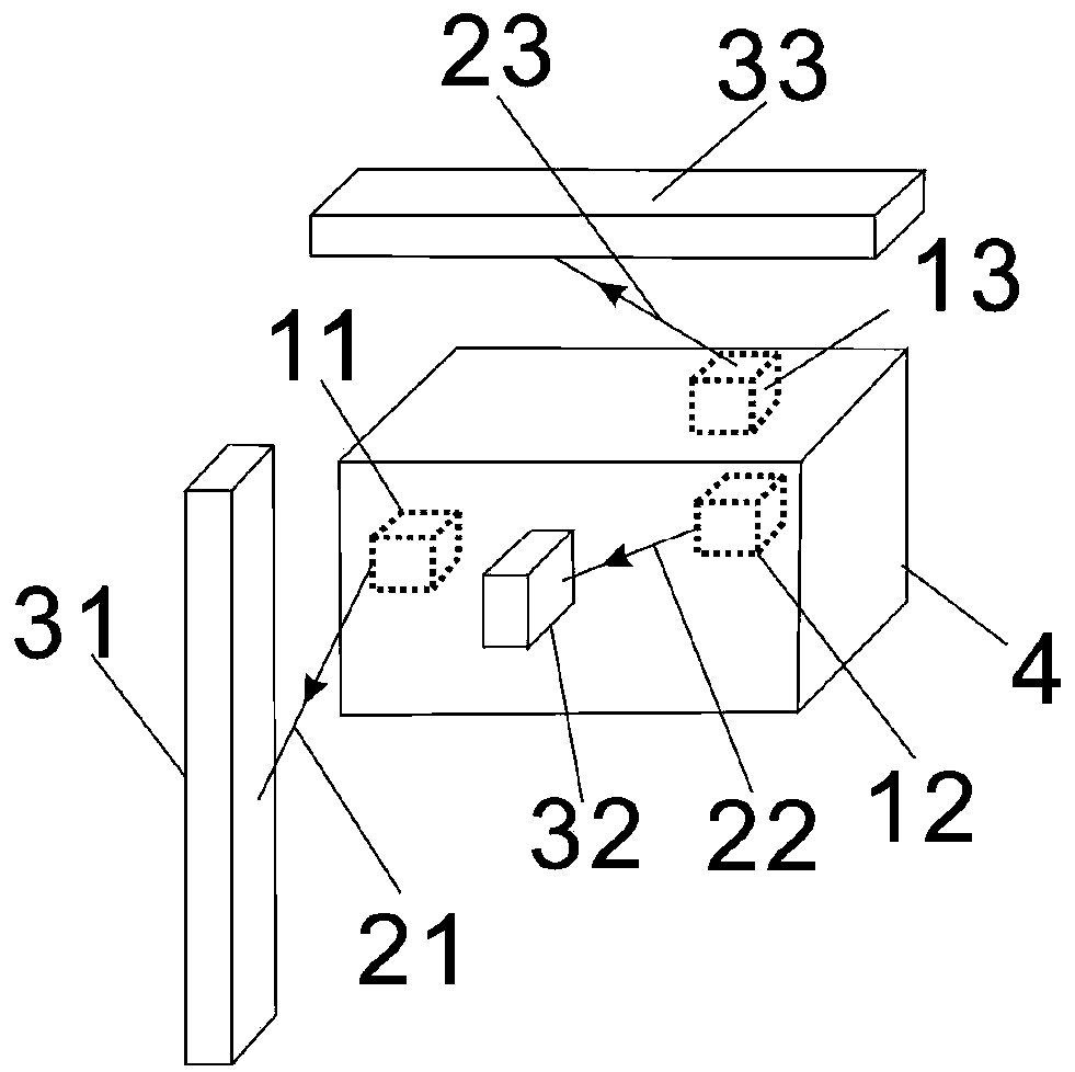
[0062] Such as figure 1 , 2 As shown, a direct-incidence optical arm magnified 3D scanning probe includes:

[0063] Three laser sources, namely laser source one 11, laser source two 12 and laser source three 13, respectively generate three laser beams, namely laser beam one 21, laser beam two 22 and laser beam three 23;

[0064] Probe base 4, said probe base 4 is provided with a laser source 11, a laser source 2 12 and a laser source 3 13, and a measuring rod 6 and a measuring ball 7 for detection;

[0065] Three photodetectors, i.e. photodetector one 31, photodetector two 32 and photodetector three 33, are respectively used to receive laser beam one 21, laser beam two 22 and laser beam three 23;

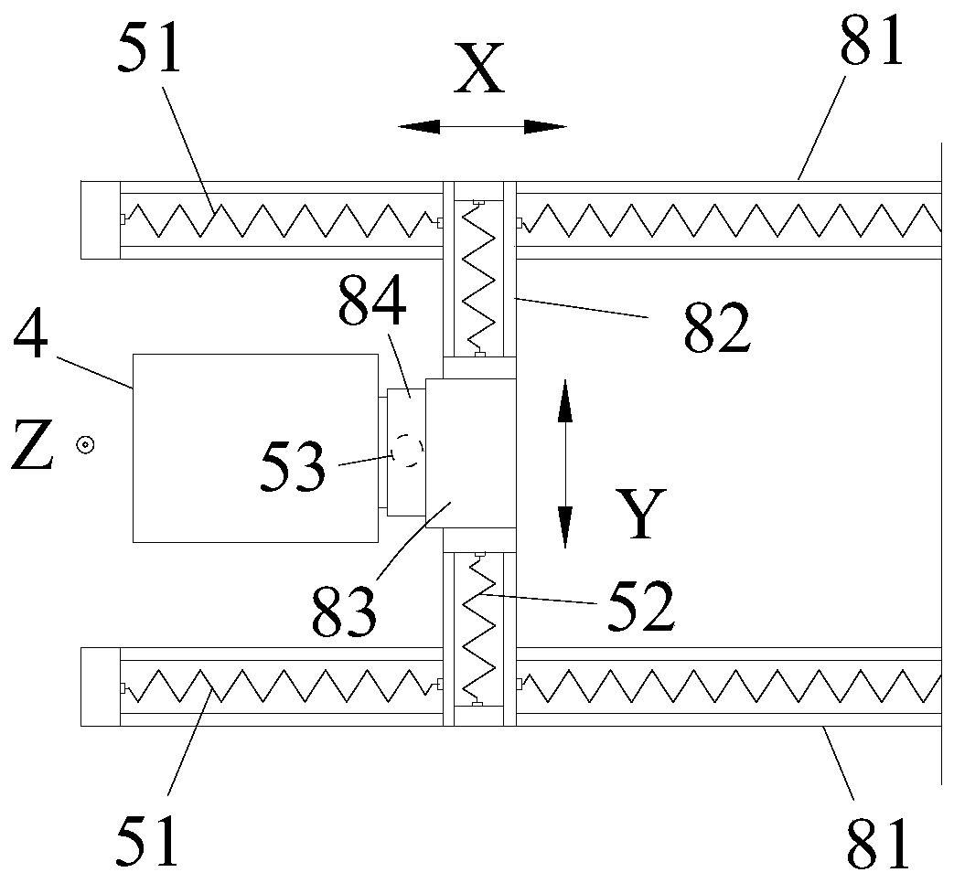
[0066] A translation component, used to make the probe base 4 move linearly;

[0067] A recovery component, used to return the probe base 4 to its initial position;

[0068] The processing system calculates and obtains the measuring ball 7 according to the incident position chan...

Embodiment 2

[0083] Such as Figure 7 As shown, a direct-incidence optical arm magnified 3D scanning probe includes:

[0084] Three laser sources, namely laser source one 11, laser source two 12 and laser source three 13, respectively generate three laser beams, namely laser beam one 21, laser beam two 22 and laser beam three 23;

[0085] Three photodetectors, i.e. photodetector one 31, photodetector two 32 and photodetector three 33, are respectively used to receive laser beam one 21, laser beam two 22 and laser beam three 23;

[0086] Probe base 4, said probe base 4 is provided with a photodetector 1 31, a photodetector 2 32 and a photodetector 3 33, and a measuring rod 6 and a measuring ball 7 for detection;

[0087] A translation component, used to make the probe base 4 move linearly;

[0088] A recovery component, used to return the probe base 4 to its initial position;

[0089] The processing system calculates and obtains the measuring ball 7 according to the incident position cha...

Embodiment 3

[0098] A direct-incidence optical arm magnified three-dimensional scanning measuring head, like Embodiment 1, includes:

[0099] Such as Figure 1-7 As shown, three laser sources, namely laser source one 11, laser source two 12 and laser source three 13, respectively generate three laser beams, namely laser beam one 21, laser beam two 22 and laser beam three 23;

[0100] Probe base 4, including measuring rod 6 and measuring ball 7 for detection;

[0101] The measuring head base 4 can be provided with three laser sources, and can also be provided with three photodetectors;

[0102] Three photodetectors, i.e. photodetector one 31, photodetector two 32 and photodetector three 33, are respectively used to receive laser beam one 21, laser beam two 22 and laser beam three 23;

[0103] The translation component and the recovery component are used to make the probe base 4 move linearly to change the incident point position of the laser beam corresponding to the photodetector;

[01...


PUM


Abstract

The present invention disclosed a large three -dimensional scanning header of the directly incident light arm, including: three laser sources used to launch three laser beams;There are laser sources or photoelectric detectors; three photoelectric detectors used to receive three incident laser beams; used to make the measured head base for translation components;Components; Calculate the processing system for the three -dimensional transfer value of the ball test.The new three -dimensional scanning header can obtain the measurement of the header in the three different linear directions through the three photoelectric detectors, and then obtain a more accurate measurement coordinate of the measurement of the measurement.This new three -dimensional scanning head improves measurement accuracy, simplifies the structure, reduces production costs, and is easy to process and manufacture in batches.

Description

technical field [0001] The invention relates to the technical field of precision measurement, in particular to a direct-incidence optical arm amplified three-dimensional scanning measuring head. Background technique [0002] The probe is one of the key components of the precision measuring instrument. As a sensor, it provides the geometric position information of the workpiece to be measured. The development level of the probe directly affects the measurement accuracy and efficiency of the precision measuring instrument. Precision probes are usually divided into contact probes and non-contact probes, of which contact probes are divided into mechanical probes, trigger probes and scanning probes; non-contact probes are divided into laser probes probes and optical video probes. [0003] The mechanical probe is an earlier type of probe used in precision measuring instruments. The probe is used for position measurement through direct contact between the probe end and the workpi...

Claims


Application Information

Patent Timeline
Patent Type & Authority Patents(China)
IPC IPC(8): G01B11/00
CPCG01B11/007G01B5/012
Inventor 张白牛勇吴国强
Owner 山东信开源科技创新发展有限责任公司
Why Eureka
Try Eureka