Catheter with deflectable front end
A technology for catheters and operations, which is applied in the field of catheters and can solve problems such as bending of inflexible parts
- Summary
- Abstract
- Description
- Claims
- Application Information
AI Technical Summary
Problems solved by technology
Method used
Image

Examples
no. 1 Embodiment approach
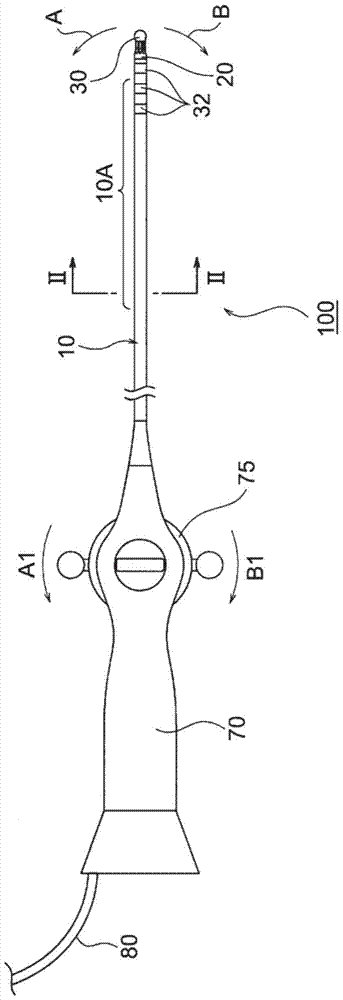
[0057] The electrode catheter 100 of one embodiment of the catheter with a deflectable tip of the present invention is used, for example, in the diagnosis or treatment of cardiac arrhythmia.
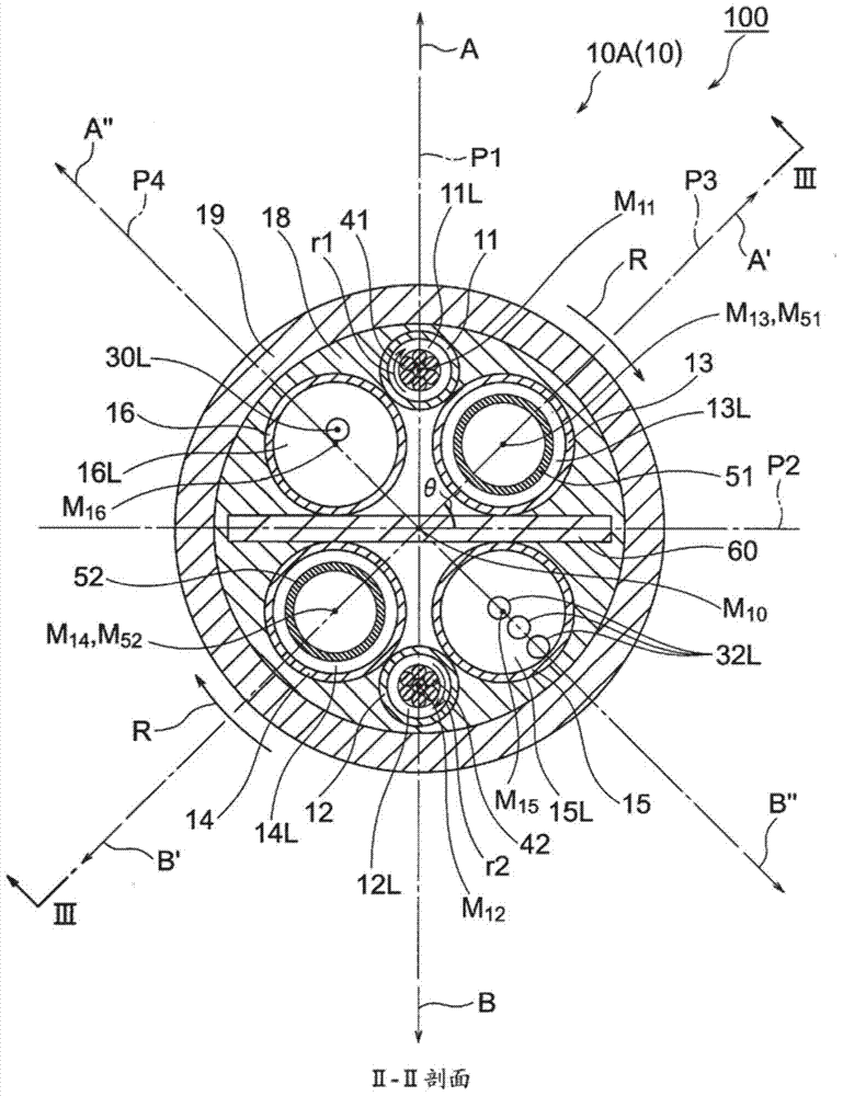
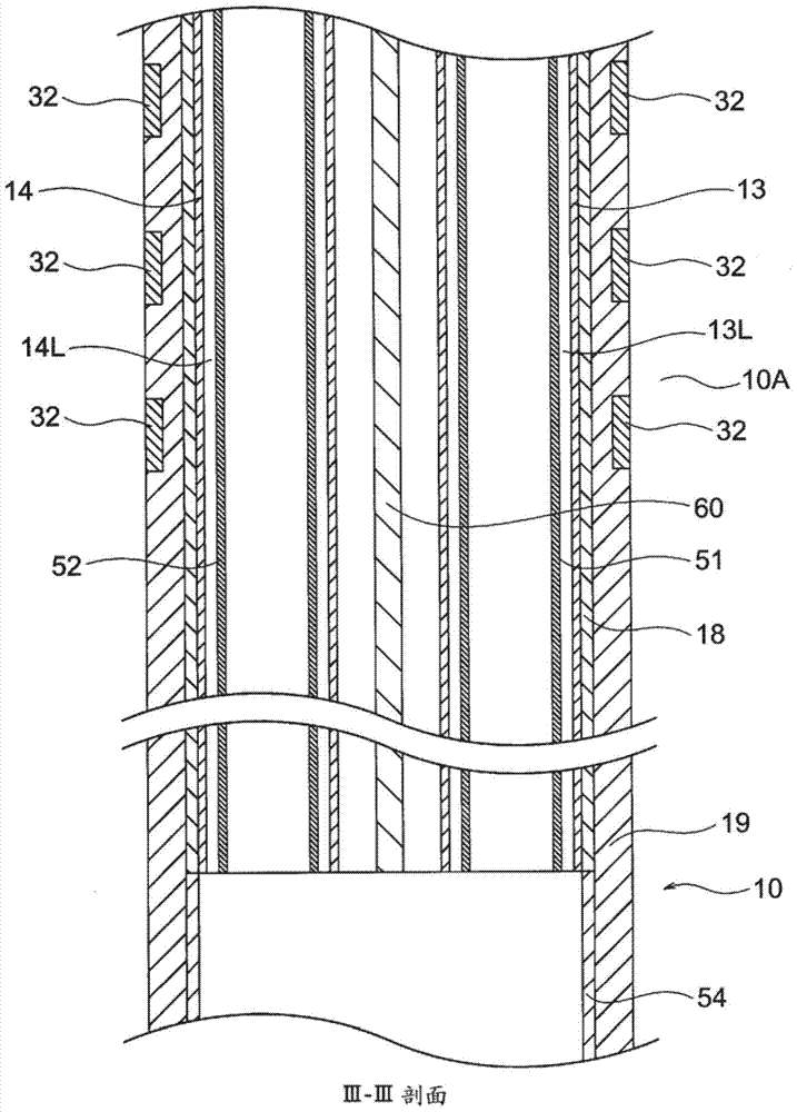
[0058] Figure 1 ~ Figure 3 The illustrated electrode catheter 100 of this embodiment includes: a catheter shaft 10 having a flexible portion 10A at the front end; a filling member 20 connected to the front end of the catheter shaft 10; The front end electrode 30 of the catheter shaft 10; the three annular electrodes 32 assembled on the front end flexible part 10A of the catheter shaft 10; The front end flexible part 10A faces the first direction ( figure 1 as well as figure 2 The direction shown by the middle arrow A) is deflected and inserted into the inside of the catheter shaft 10, the front end of the first operation wire 41 is connected and fixed to the perfusion part 20, and the rear end can be used for pulling operation; the second The operation thread 42 is made of a twiste...
no. 2 Embodiment approach
[0145] Figure 4 as well as Figure 5 The illustrated electrode catheter 200 of this embodiment includes: a catheter shaft 210 having a flexible distal portion 210A; a distal electrode 230 fixed to the distal end of the catheter shaft 210; The three ring-shaped electrodes 232 of the flexible part 210A of the front end; the first operation wire 241, which is made of a twisted thread (left twist), so that the flexible part 210A of the front end of the catheter shaft 210 faces the first direction ( Figure 4 as well as Figure 5 The direction shown by the middle arrow A) is deflected and inserted into the inside of the catheter shaft 210, the front end of the first operation wire 241 is connected and fixed to the front end electrode 230, and the rear end can be used for pulling operation; The operation thread 242 is made of a twisted thread (left twist) so that the flexible portion 210A of the distal end of the catheter shaft 210 faces the second direction ( Figure 4 as well ...
no. 3 Embodiment approach
[0190] exist Figure 6 The electrode catheter 300 of the present embodiment, which shows the cross-sectional shape of the flexible distal portion, includes: a catheter shaft 310 having a flexible distal portion 310A; a distal electrode fixed to the distal end of the catheter shaft 310; The three ring-shaped electrodes assembled on the flexible portion 310A of the distal end of the catheter shaft 310; the first operation wire 341 is composed of a twisted thread (left twisted) so that the flexible portion 310A of the distal end of the catheter shaft 310 in the first direction ( Figure 6 The direction shown by the middle arrow A) is deflected and inserted into the inside of the catheter shaft 310, the front end of the first operation wire 341 is connected and fixed to the front end electrode, and the rear end can be used for pulling operation; the second operation Use thread 342, which is made of twisted yarn (left twist), so that the front end flexible portion 310A of the cath...
PUM
 Abstract
Description
Claims
Application Information
 - R&D Engineer
- R&D Manager
- IP Professional
- Industry Leading Data Capabilities
- Powerful AI technology
- Patent DNA Extraction
Browse by: Latest US Patents, China's latest patents, Technical Efficacy Thesaurus, Application Domain, Technology Topic.
© 2024 PatSnap. All rights reserved.Legal|Privacy policy|Modern Slavery Act Transparency Statement|Sitemap